
Negative pressure pneumatic conveying experiment device and experiment method

A negative pressure pneumatic conveying and experimental device technology, applied in the direction of measuring devices, testing/calibrating devices, instruments, etc., can solve problems such as weighing accuracy errors, calibration work difficulties, time and space differences, etc., and achieve the goal of improving calibration accuracy Effect

Pending Publication Date: 2019-06-07
OCEANOGRAPHIC INSTR RES INST SHANDONG ACAD OF SCI +1
View PDF1 Cites 1 Cited by
  • Summary
  • Abstract
  • Description
  • Claims
  • Application Information

AI Technical Summary

Problems solved by technology

[0004] There are major defects in the way of weighing the feed amount on site, which seriously affects the stable and safe operation of the production process
First of all, in the actual production process of material weighing, the pipeline for conveying materials is always connected with the silo, which introduces errors for the accuracy of weighing; secondly, the actual production of material conveying pipelines is arranged according to the site restrictions, and there may not be a place to install solid mass The flow meter brings difficulties to the calibration work; finally, there are time and space differences between the reduction of the material in the silo and the mass flow rate of the material in the material delivery pipeline, and real-time online calibration cannot be accurately realized
East China University of Science and Technology designed a solid mass flowmeter calibration device and its use method and the system containing it (CN200910050837.6), which is a positive pressure pneumatic conveying system, and it is difficult to complete the calibration of the mass flowmeter in the negative pressure pneumatic conveying system

Method used


Image

  • Negative pressure pneumatic conveying experiment device and experiment method

Examples


Embodiment Construction

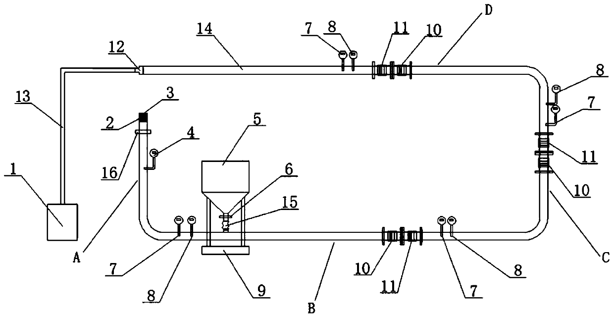
[0022] The negative pressure pneumatic conveying experimental device and experimental method of the present invention will be described in detail below in conjunction with the accompanying drawings and embodiments.

[0023] The negative pressure pneumatic conveying experimental device of the present invention is structurally connected as figure 1 As shown, it mainly includes the following structures: industrial vacuum cleaner 1, wind speed sensor 4, feeder 5, temperature sensor 7, pressure sensor 8, electronic scale 9, sight glass 10, mass flow meter 11, and material conveying pipeline 14.

[0024] The feeder 5 is connected to the front end of the material conveying pipeline 14 through a flexible connecting pipe 15 . A check valve 6 is installed at the connection between the feeder 5 and the flexible connecting pipe 15 . Feeding machine 5 is placed on the electronic scale 9. As a preferred mode of the present invention, the motor of the feeder 5 is a variable frequency motor...


PUM


Abstract

The invention belongs to the technical field of pneumatic pipeline conveying and relates to a negative pressure pneumatic conveying experiment device and experiment method. The negative pressure pneumatic conveying experiment device comprises a negative pressure device, a conveying pipeline and a feeding machine. The feeding machine is arranged at the front end of the conveying pipeline, and the negative pressure device is arranged at the tail end of the conveying pipeline. The conveying pipeline between the feeding machine and the negative pressure device is provided with a mass flowmeter. Anelectronic scale is arranged under the feeding machine. The negative pressure pneumatic conveying experiment device solves the problem of experimental errors caused by the factor of scale ratio of experiment equipment and practical engineering equipment, can simulate the flow state of materials in the pipeline under different wind speeds and feeding amounts and improves checking accuracy of the material mass flowmeter.

Description

technical field [0001] The invention belongs to the technical field of pneumatic pipeline transportation, and relates to a negative pressure pneumatic transportation experimental device and an experimental method. Background technique [0002] Pneumatic conveying technology refers to the use of the energy of airflow to transport granular materials along the direction of airflow in a closed pipeline. According to the different pressure characteristics, the pneumatic conveying system is divided into a positive pressure pneumatic conveying system and a negative pressure pneumatic conveying system. Negative pressure pneumatic conveying is to use the fan at the end of the system to suck the air in the system to form a negative pressure airflow. The airflow carries the material from the suction nozzle into the system and reaches the end point, and finally the air is discharged into the atmosphere after filtration and separation. Because all the air along the pipeline leaks inward...

Claims


Application Information

Patent Timeline
Patent Type & Authority Applications(China)
IPC IPC(8): G01F25/00
Inventor 李遵伟王虎杨长厚贾欣鑫王雷王艳龙张浩李显昭赵燕博刘杰苏晓飞
Owner OCEANOGRAPHIC INSTR RES INST SHANDONG ACAD OF SCI
Learn More