
Turbofan engine

A technology of turbofan engine and turbine, which is applied in the direction of machine/engine, mechanical equipment, gas turbine device, etc., to achieve the effect of increasing thrust-to-weight ratio, increasing thrust and reducing weight

Active Publication Date: 2019-06-07
AECC SHENYANG ENGINE RES INST
View PDF5 Cites 13 Cited by
  • Summary
  • Abstract
  • Description
  • Claims
  • Application Information

AI Technical Summary

Problems solved by technology

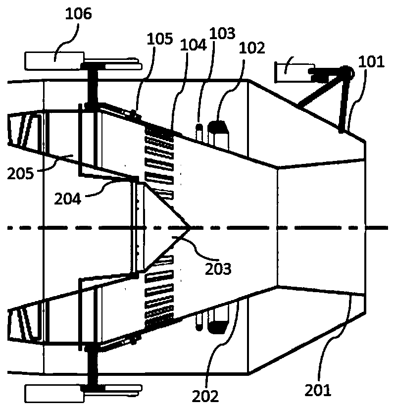
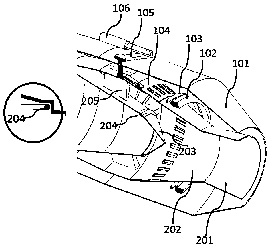
[0008] The purpose of this application is to provide a turbofan engine to solve at least one of the above-mentioned problems

Method used


Image

  • Turbofan engine
  • Turbofan engine
  • Turbofan engine

Examples


Embodiment Construction

[0035] In order to make the purpose, technical solution and advantages of the application more clear, the technical solution in the embodiment of the application will be described in more detail below in conjunction with the drawings in the embodiment of the application. In the drawings, the same or similar reference numerals denote the same or similar elements or elements having the same or similar functions throughout. The described embodiments are some, but not all, embodiments of the application. The embodiments described below by referring to the figures are exemplary, and are intended to explain the present application, and should not be construed as limiting the present application. Based on the embodiments in this application, all other embodiments obtained by persons of ordinary skill in the art without creative efforts fall within the protection scope of this application. Embodiments of the present application will be described in detail below in conjunction with th...


PUM


Abstract

The invention discloses a turbofan engine and belongs to the technical field of design of an aero turbofan engine. The engine comprises a second afterburner (2) and a first afterburner (1), wherein the second afterburner (2) comprises an afterburner inner spraying pipe and a main force exerting cavity; the afterburner inner spraying pipe is fixedly connected with the back end of an inner cylinder;the main force exerting cavity is positioned in the afterburner inner spraying pipe; a through hole is formed in the afterburner inner spraying pipe; the first afterburner (1) comprises an afterburner outer spraying pipe and an auxiliary force exerting cavity; the afterburner outer spraying pipe is fixedly connected with the back end of an outer cylinder; the auxiliary force exerting cavity is positioned between the afterburner outer spraying pipe and the afterburner inner spraying pipe; the first afterburner (1) also comprises a baffle; the baffle is controlled by an adjusting mechanism to close or open the through hole in the afterburner inner spraying pipe; and the opening section of the tail end of the afterburner outer spraying pipe is adjustable. The length and the weight of the afterburner are reduced by adjusting the afterburning condition of the main force exerting cavity and the auxiliary force exerting cavity.

Description

technical field [0001] The application belongs to the technical field of aviation turbofan engine design, in particular to an ultra-short, light-weight, high-efficiency afterburning concept turbofan engine. Background technique [0002] The afterburning turbofan engine generally refers to the addition of an afterburner at the end of a conventional engine. The air in the external duct and the gas after the turbine enter the afterburner together and burn again after fuel injection, so that the thrust can be greatly increased, such as Figure 6 Shown is a schematic diagram of the structure of the traditional afterburning turbofan engine M88 ohm. The afterburning turbofan engine generally consists of a fan 7, a high-pressure compressor 5, a main combustion chamber 4, a high and low pressure turbine 3, an afterburner 8, a jet Tube 9 and so on are connected in series. Generally, the outlet of the low-pressure turbine is the inlet of the afterburner, and the outlet of the afterburn...

Claims


Application Information

Patent Timeline
Patent Type & Authority Applications(China)
IPC IPC(8): F02C3/14F02K3/06F02K3/10F02K3/11
Inventor 邓洪伟李泳凡李宏新高东武尚守堂
Owner AECC SHENYANG ENGINE RES INST
Learn More