
Self-balancing type inertia damper with reciprocating screw rod

A self-balancing, damper technology, used in protective buildings/shelters, building components, earthquake-proof and other directions, can solve the problem that the plate and pendulum dampers do not meet the requirements, cannot use pure tension systems, and cannot be provided by cables. Braking torque and other problems, to achieve the effect of complete separation of damping and stiffness, and high damping coefficient

Pending Publication Date: 2019-06-07
TONGJI UNIV
View PDF0 Cites 7 Cited by
  • Summary
  • Abstract
  • Description
  • Claims
  • Application Information

AI Technical Summary

Problems solved by technology

The pure tension system of the central energy-dissipating member is a better damper installation method to meet the needs of rapid seismic reinforcement. If the eddy current damper can be introduced into the system for use, the easy installation performance of the eddy current damper will be better utilized. However, since the cable can only provide tension to the central energy-dissipating member and cannot limit the rotation, performance requirements such as light weight and self-balancing are put forward for the eddy current damper. Obviously, the plate-type and pendulum-type dampers do not meet the requirements. At present, there are screw rods Although the rotary eddy current damper has a certain speed amplification capability, the threaded screw type rotary eddy current damper must use the fixed end to limit the rotation of the screw and the stator at the same time, so that the damper can work, which makes it It cannot be used in a pure tension system, the connection of the cable cannot provide such a braking torque

Method used


Image

  • Self-balancing type inertia damper with reciprocating screw rod
  • Self-balancing type inertia damper with reciprocating screw rod
  • Self-balancing type inertia damper with reciprocating screw rod

Examples


Embodiment Construction

[0038] The technical solutions provided by the present invention will be further described below in conjunction with specific embodiments and accompanying drawings. The advantages and features of the present invention will become clearer in conjunction with the following description.

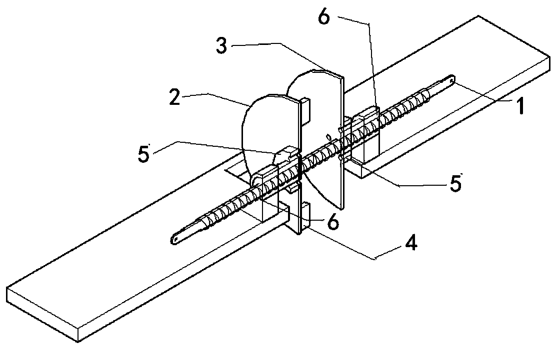
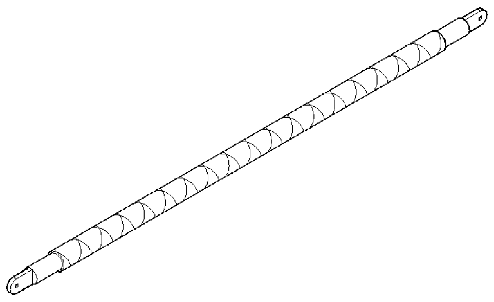
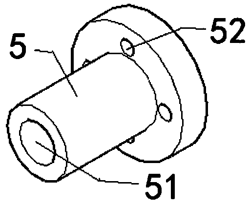
[0039] like Figure 1 to Figure 6 As shown, the present invention provides a self-balancing inertia damper using a reciprocating screw rod, including a reciprocating screw rod 1 , a magnet disk 2 , a conductor disk 3 , a permanent magnet 4 , a screw nut 5 , and a bearing support 6 .

[0040] Wherein, the reciprocating screw rod 1 is a bidirectional threaded screw rod provided with positive and negative threads, and the positive and negative threads are arranged across the entire course on the reciprocating screw rod 1; A screw nut 5 corresponding to the thread is provided, and two screw nuts 5 are respectively engaged and connected with the positive thread and the negative thread of the recipro...


PUM


Abstract

The invention belongs to the technical field of energy dissipation and seismic reduction of engineering structures, and provides a self-balancing type inertia damper with a reciprocating screw rod. The self-balancing type inertia damper comprises the reciprocating screw rod, magnet discs, conductor discs, a permanent magnet, a screw rod nut and a bearing support. The self-balancing type inertia damper utilizes the characteristics that the reciprocating screw rod arranges two threads with the same pitch and opposite rotation directions on the whole stroke, and a pair of magnet discs and a pairof conductor discs are arranged in pairs, so that the action torque and the reaction torque of the eddy current effect act on the reciprocating screw rod at the same time and offset each other; on theone hand, the damping coefficient is simple and easy to adjust, the damping and the stiffness are completely separated, on the other hand, the self-balancing performance that a common spiral rotary damper does not have is achieved; and the magnet discs and the conductor discs rotate together and act on the reciprocating screw rod, the rotation effects cancel each other, the longitudinal axial force is doubled, so that the eddy current effect is doubled, and a higher damping coefficient is obtained.

Description

technical field [0001] The invention belongs to the technical field of energy dissipation and shock absorption of engineering structures, and in particular relates to a self-balancing inertial damper using a reciprocating screw rod. Background technique [0002] The energy-dissipating and shock-absorbing technology of engineering structures is to add energy-dissipating and shock-absorbing devices to the structure, and reduce the dynamic response of the structure itself through the energy-dissipating effect of the additional shock-absorbing devices, ensuring the safety, comfort and normal usability of the structure and other functional requirements. [0003] At present, the eddy current damper is mainly used as the damping element of the tuned mass damper and is gradually being applied in the field of passive vibration control of civil engineering structures. [0004] The eddy current damper, as a new and efficient structural passive vibration control method, is an energy-co...

Claims


Application Information

Patent Timeline
IPC IPC(8): E04B1/98E04H9/02
Inventor 谢丽宇薛智奇薛松涛
Owner TONGJI UNIV
Learn More