Ring grinder structure

A technology of ring rolling machine and driving mechanism, applied in metal rolling and other directions, can solve problems such as unfavorable implementation of movable seat movement, increase in weight and volume of movable seat, etc., and achieve outstanding substantive characteristics, good balance and good The effect of grinding ring work

Active Publication Date: 2019-06-07
广东毅马集团有限公司 +8
View PDF6 Cites 0 Cited by
  • Summary
  • Abstract
  • Description
  • Claims
  • Application Information

AI Technical Summary

Problems solved by technology

[0002] At present, the power rollers of the existing ring rolling machines are installed on the movable seat, and the movable seat moves up and down or left and right to make the power roller gradually touch the ring to be rolled, and the movable seat needs to be provided with a driving power roller The rotating mechanism, like this, increases the weight and volume of the movable seat, which is unfavorable for the specific implementation and the movement of the movable seat

Method used


Image

  • Ring grinder structure
  • Ring grinder structure

Examples


Embodiment Construction

[0017] The features of the present invention and other relevant features are described in further detail below through the embodiments, so as to facilitate the understanding of those skilled in the art:

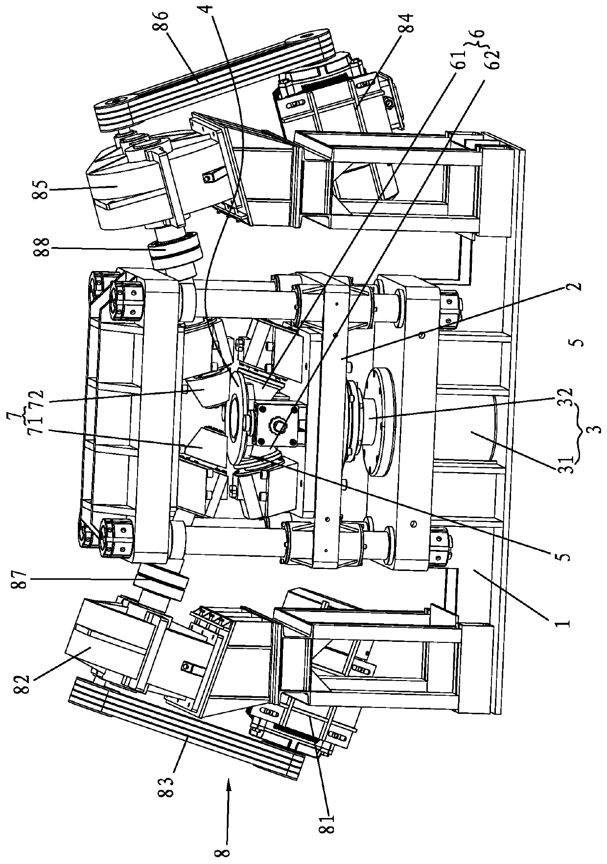
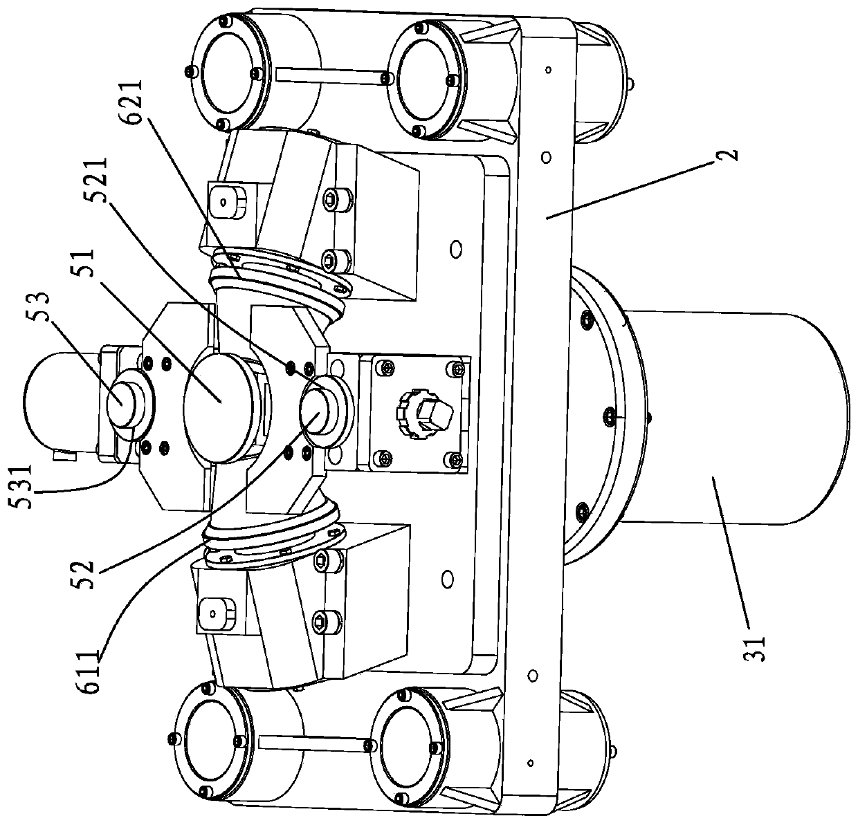
[0018] Such as Figure 1-Figure 2 As shown, a ring rolling machine structure includes a bracket 1, and the bracket 1 is provided with a vertical sliding seat 2 and a first driving mechanism for driving the vertical sliding seat 2 to slide up and down relative to the bracket 1 3. The vertical sliding seat 2 is provided with a limit support structure 5 for limit support of the annular end plate 4 and a driven tapered roller group 6 rotatably installed for rotational contact with the lower end surface of the annular end plate 4, The bracket 1 is also rotatably installed with a driving tapered roller group 7 located above the annular end plate 4 for rotating contact with the upper end surface of the annular end plate 4 and a second roller for driving the driving tapered roller gr...


PUM


Abstract

The invention discloses a ring grinder structure. An active bevel roller set is not arranged on a vertical slide base, and has no need to move up and down relative to a bracket, so that the trouble ofarranging a second driving mechanism, moving with the vertical slide base, on the vertical slide base, to drive the driving bevel roller set to rotate is prevented, and prominent substantive featuresand prominent advancements are achieved; in addition, the second driving mechanism is arranged on the bracket conveniently; the second driving mechanism with high power is selected as needed; a limiting support structure and a driven bevel roller set are both arranged on the vertical slide base; and a first driving mechanism drives the vertical slide base to move up, so that the upper end surfaceof an annular end surface on the limiting support structure can be contacted with the driving bevel roller set on the upper side, and the driving is convenient.

Description

technical field [0001] The invention relates to a ring rolling machine structure. Background technique [0002] At present, the power rollers of the existing ring rolling machines are installed on the movable seat, and the movable seat moves up and down or left and right to make the power roller gradually touch the ring to be rolled, and the movable seat needs to be provided with a driving power roller The rotating mechanism, like this, increases the weight and volume of the movable seat, which is unfavorable for the specific implementation and the movement of the movable seat. [0003] Therefore, how to overcome the above existing defects has become an important issue to be solved urgently by those skilled in the art. Contents of the invention [0004] The invention overcomes the disadvantages of the above technologies and provides a ring rolling machine structure. [0005] To achieve the above object, the present invention adopts the following technical solutions: [...

Claims


Application Information

Patent Timeline
Patent Type & Authority Applications(China)
IPC IPC(8): B21H1/06
Inventor 尹文鹤
Owner 广东毅马集团有限公司
Why Eureka
Try Eureka