
A high-voltage frequency converter optical signal loop test method and system

A high-voltage frequency converter and loop test technology, which is applied in transmission systems, electromagnetic wave transmission systems, electrical components, etc., can solve problems such as large errors, affecting communication functions, and high costs

Inactive Publication Date: 2019-06-04
DAYU ELECTRIC
View PDF4 Cites 1 Cited by
  • Summary
  • Abstract
  • Description
  • Claims
  • Application Information

AI Technical Summary

Problems solved by technology

When the above circuit devices are abnormal, it will affect the communication function
[0004] Existing methods for testing faulty power units include directly observing whether a communication fault is reported when the high-voltage frequency converter is working, or using a specially made optical fiber signal loop test tool for testing. The former has large errors and low efficiency, while the latter requires each Each power unit is tested for communication function one by one, the efficiency is low, and the test tooling needs to be invested and developed, and the cost is high. In addition, because the voltage of the high-voltage inverter is as high as 6kV or 10kV, in order to ensure the safety of the operator, every time Power-on and power-off operations must comply with safety regulations and procedures, and testing takes a lot of time

Method used


Image

  • A high-voltage frequency converter optical signal loop test method and system
  • A high-voltage frequency converter optical signal loop test method and system
  • A high-voltage frequency converter optical signal loop test method and system

Examples


Embodiment Construction

[0060] The present invention will be described in further detail below in conjunction with the accompanying drawings and embodiments.

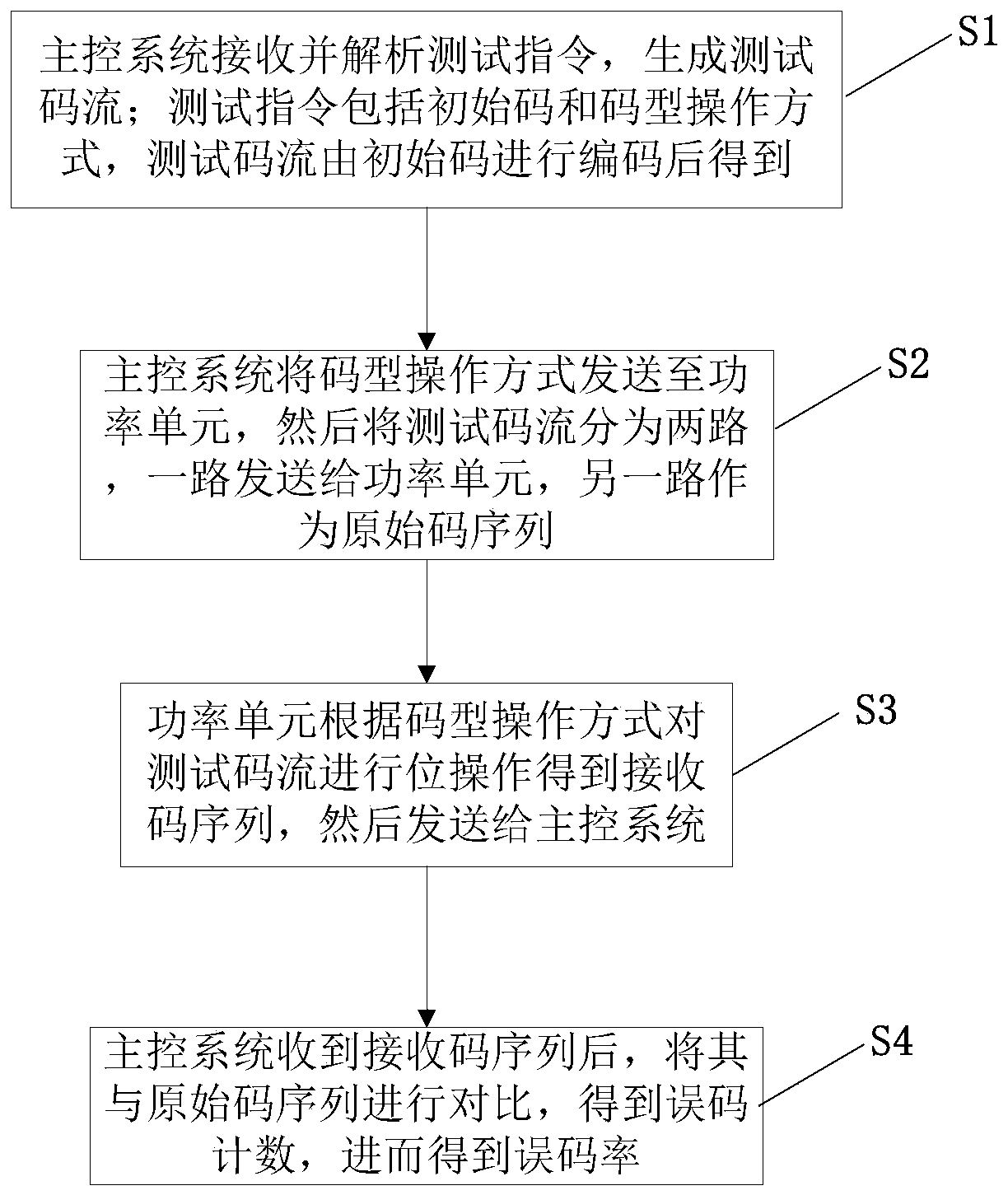
[0061] see figure 1 As shown, the embodiment of the present invention provides a method for testing the optical signal loop of a high-voltage frequency converter, which is used to test the optical fiber communication function between the main control system and the power unit of the high-voltage frequency converter, including the following steps:

[0062]S1. The main control system receives and parses the test command to generate a test code stream; the test command includes the initial code and the mode of operation of the code pattern, and the test code stream is obtained by encoding the initial code. Wherein, the initial code generates a test code stream according to a pseudo-random binary sequence, and the test code stream is a pseudo-random code PRBS7 code stream.

[0063] S2. The main control system sends the code pattern operation mode...


PUM


Abstract

The invention discloses a method and a system for testing an optical signal loop of a high-voltage frequency converter, which relate to the technical field of communication testing of high-voltage frequency converters and the method comprises the following steps that: a main control system receives and analyzes a test instruction to generate a test code stream; Wherein the test instruction comprises an initial code and a code type operation mode, and the test code stream is obtained by encoding the initial code; The main control system sends the code pattern operation mode to the power unit, and then divides the test code stream into two paths, one path is sent to the power unit, and the other path is used as an original code sequence; The power unit performs bit operation on the test codestream according to the code pattern operation mode to obtain a receiving code sequence, and then sends the receiving code sequence to the main control system; And after receiving the receiving codesequence, the main control system compares the receiving code sequence with the original code sequence to obtain an error code count and an error rate. The error rate is calculated by comparing the generated original code sequence with the receiving code sequence returned by the power unit through the main control system, and whether the corresponding power unit is in normal communication with themain control system or not is judged according to the error rate.

Description

technical field [0001] The invention relates to the technical field of high-voltage frequency converter communication testing, in particular to a method and system for testing an optical signal loop of a high-voltage frequency converter. Background technique [0002] The high-voltage inverter consists of a main control system and multiple power units. The main control system and each power unit communicate through a pair of optical fibers to transmit the control signals of the power units. In the fields of electric power, chemical industry, coal mining, metallurgy and other industrial production, high-voltage frequency converters are required to have extremely high reliability, and whether the high-voltage frequency converter can work normally depends on whether the communication circuit can transmit data correctly. [0003] The optical fiber communication circuit between the main control system and each power unit is composed of many circuits, mainly composed of the serial ...

Claims


Application Information

Patent Timeline
Patent Type & Authority Applications(China)
IPC IPC(8): H04B10/079
Inventor 毛康宇吴德朝吴仕福肖少兵王发刚王琴
Owner DAYU ELECTRIC
Learn More