
Laser radar, laser radar system for reducing ambient light interference and detection method thereof

A laser radar and detection method technology, applied in the laser radar system and its detection field, can solve the problems that affect the detection of the target object by the laser radar, the target object cannot be detected by the laser radar, and reduce the service life of the laser radar, so as to improve the strength, The effect of improving accuracy and prolonging service life

Inactive Publication Date: 2019-06-04
NINGBO SUNNY AUTOMOTIVE OPTECH
View PDF6 Cites 16 Cited by
  • Summary
  • Abstract
  • Description
  • Claims
  • Application Information

AI Technical Summary

Problems solved by technology

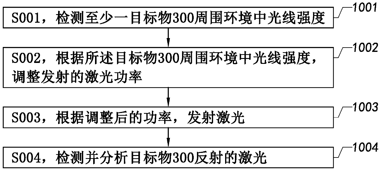
The existing laser radar needs to transmit laser light to the target object, and when the laser radar is working, the light in the environment where the target object is located will be reflected by the target object, which will affect the detection of the target object by the laser radar, especially where the target object is located. When the light intensity in the environment is strong, the excessive ambient light will cause the target object to be blurred, and may even cause the target object to be unable to be detected by the laser radar, which will affect the accuracy of the laser radar detection.
And if the light intensity in the environment where the target is located is low, then there is no need for the lidar to emit a stronger laser, but if the lidar still uses the same intensity of detection light as when the light intensity in the environment where the target is located is stronger Detecting the target will reduce the service life of the lidar
In other words, when the existing lidar detects the target, the light in the surrounding environment of the target will interfere with it

Method used


Image

  • Laser radar, laser radar system for reducing ambient light interference and detection method thereof
  • Laser radar, laser radar system for reducing ambient light interference and detection method thereof
  • Laser radar, laser radar system for reducing ambient light interference and detection method thereof

Examples


Embodiment Construction

[0064] The following description serves to disclose the present invention to enable those skilled in the art to carry out the present invention. The preferred embodiments described below are only examples, and those skilled in the art can devise other obvious variations. The basic principles of the present invention defined in the following description can be applied to other embodiments, variations, improvements, equivalents and other technical solutions without departing from the spirit and scope of the present invention.

[0065] Those skilled in the art should understand that in the disclosure of the present invention, the terms "vertical", "transverse", "upper", "lower", "front", "rear", "left", "right", " The orientation or positional relationship indicated by "vertical", "horizontal", "top", "bottom", "inner", "outer", etc. is based on the orientation or positional relationship shown in the drawings, which are only for the convenience of describing the present invention...


PUM


Abstract

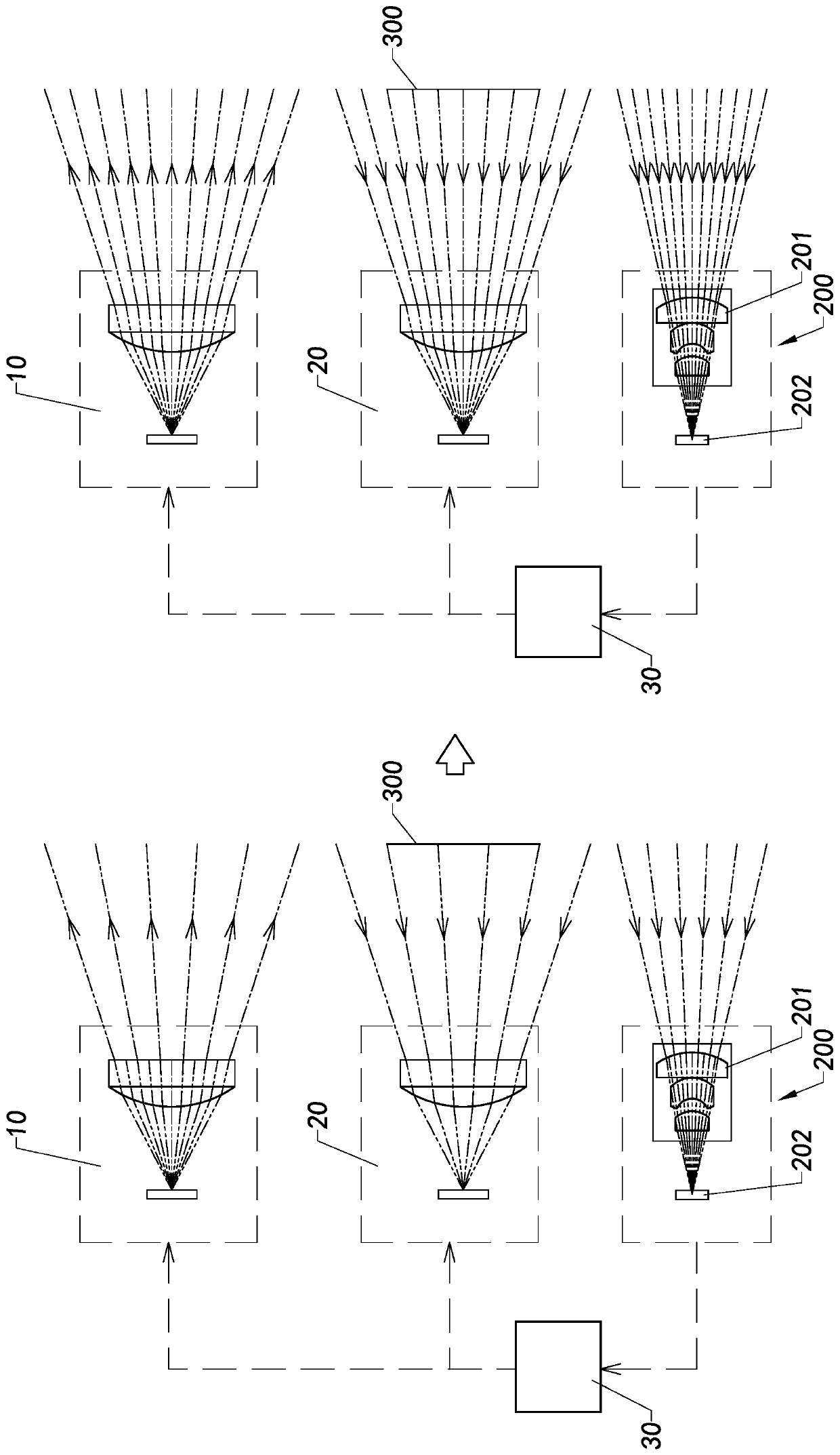
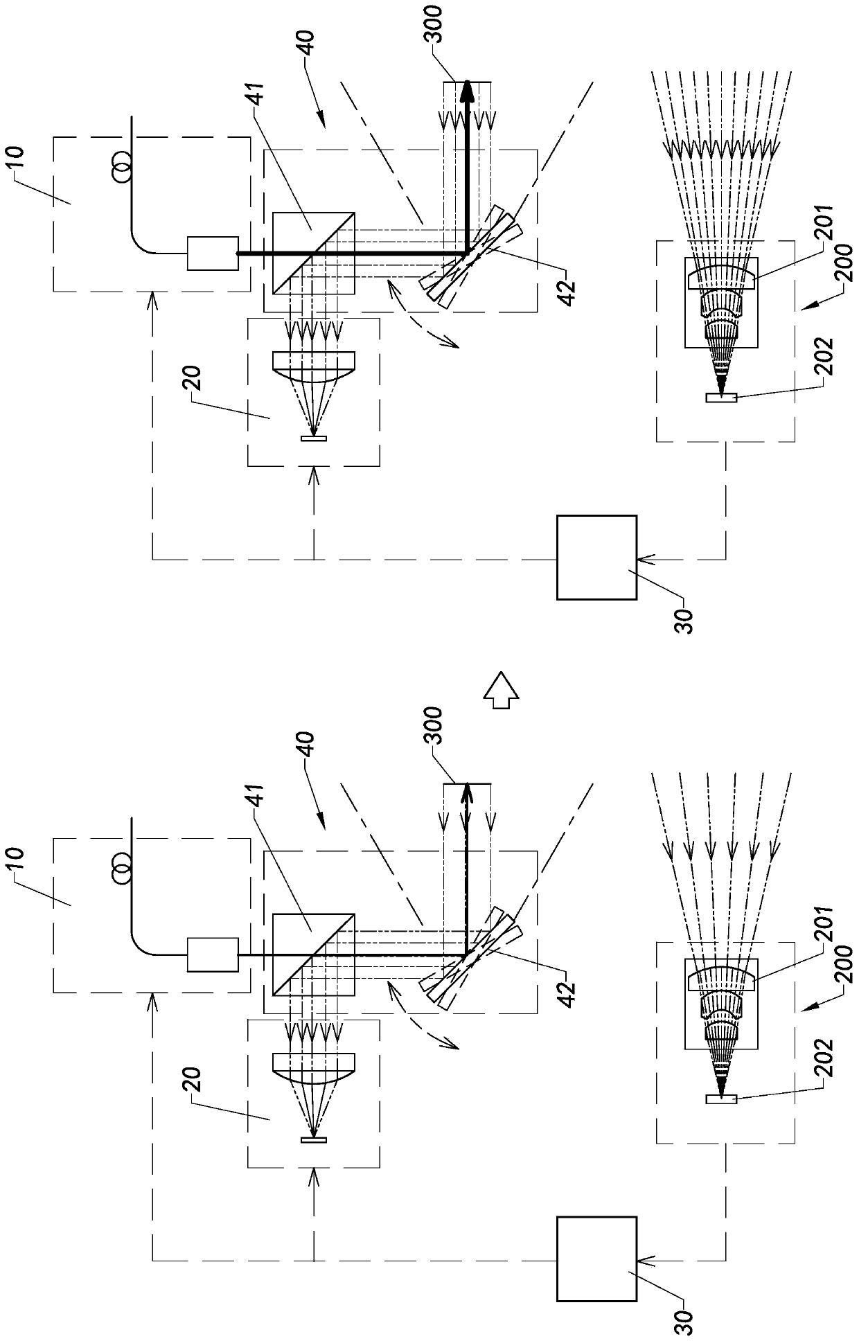
The invention provides a laser radar, a laser radar system for reducing an ambient light interference and a detection method thereof. The laser radar system integrates all portions. The laser radar system for reducing the ambient light interference comprises an ambient light collection module and a management module. The ambient light collection module collects an electrical signal related to surrounding ambient light intensity of a target object. The management module comprises an analysis module and a control module. The analysis module is connected to the ambient light collection module andthe control module in a communication connection mode, wherein the analysis module of the management module analyzes the acquired electrical signal and generates a control signal which is related tothe control of the laser radar. The control module controls a laser emitting end and / or a laser receiving end of the laser radar according to the control signal.

Description

technical field [0001] The invention relates to a laser detection system, in particular to a laser radar, a laser radar system and a detection method for reducing ambient light interference. Background technique [0002] Lidar is a radar system that emits laser beams to detect the position, speed and other characteristics of the target. The Lidar system obtains information such as the distance and azimuth of the target by receiving the laser signal emitted by the target. Current lidar systems include mechanical radar systems, hybrid solid-state radar systems such as MEMS lidar systems, and solid-state radar systems such as 3DFlash solid-state radar systems. [0003] The existing lidar has the advantages of active detection all-day work, strong anti-interference ability, high detection accuracy, and all-day work. The existing laser radar needs to transmit laser light to the target object, and when the laser radar is working, the light in the environment where the target obje...

Claims


Application Information

Patent Timeline
Patent Type & Authority Applications(China)
IPC IPC(8): G01S17/06G01S17/42G01S17/58G01S7/484G01S7/486G01S7/491G01S7/481
Inventor 沈阳杨佳徐超王强
Owner NINGBO SUNNY AUTOMOTIVE OPTECH
Learn More