Eureka AIR delivers breakthrough ideas for toughest innovation challenges, trusted by R&D personnel around the world.

Garment parts separation mechanism and garment parts separation method

A separation mechanism and separation method technology, applied in the field of cutting bed, can solve the problems of multi-layer fabrics and small pieces that cannot be sucked up, so as to improve the level of production automation and expand the application range

Active Publication Date: 2019-06-04
BULLMER ELECTROMECHANICAL TECH
View PDF6 Cites 0 Cited by
  • Summary
  • Abstract
  • Description
  • Claims
  • Application Information

AI Technical Summary

Problems solved by technology

There are many shortcomings in this method. One is that the suction cup can only suck a single layer of fabric, and cannot solve the problem of multi-layer fabrics.
The second is that the suction cup is only for larger pieces, and often cannot suck up small pieces.

Method used


Image

  • Garment parts separation mechanism and garment parts separation method
  • Garment parts separation mechanism and garment parts separation method
  • Garment parts separation mechanism and garment parts separation method

Examples


Embodiment 1

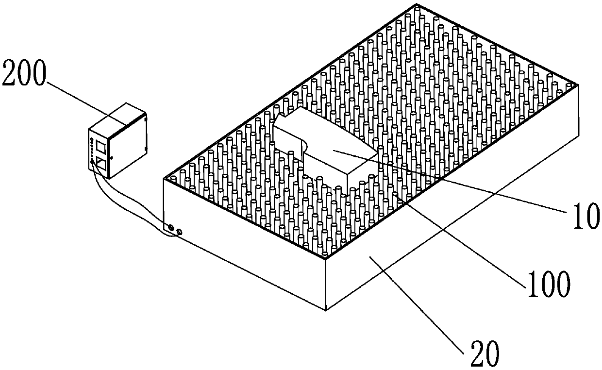
[0035] Such as Figure 1 to Figure 3 As shown, the piece separation mechanism of this embodiment is used to separate the cut piece 10 from the fabric from the fabric;

[0036] Part separation mechanism, including:

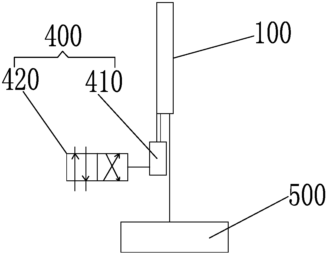
[0037] A plurality of support members 100 arranged on the top surface of the receiving platform 20, all support members 100 are arranged in a matrix, and each support member 100 can rise or fall along the vertical direction;

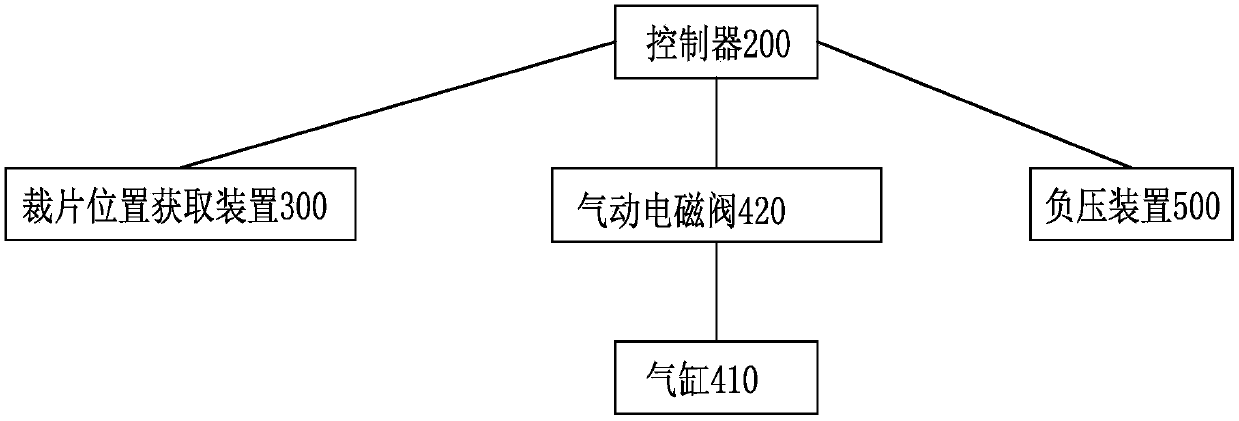
[0038] The controller 200 can separately control each support member 100 to rise or fall along the vertical direction;

[0039] The cutting piece position acquisition device 300 collects the position information of the cutting piece 10 on the receiving table 20, and transmits the position information of the cutting piece 10 to the controller 200; the controller 200 controls the support member 100 directly below the cutting piece 10 Rise or fall along the vertical direction to separate the fabric from the cut piece 10.

[0040] In the prese...


PUM

PropertyMeasurementUnit
Spacingaaaaaaaaaa
The inside diameter ofaaaaaaaaaa
Outer diameteraaaaaaaaaa

Abstract

The invention provides a garment parts separation mechanism and a garment parts separation method. The garment parts separation mechanism comprises: a plurality of supports arranged at the top of a collecting table, wherein all the supports are in matrix arrangement and each support can rise or fall in the vertical direction; a controller which can control every support to rise or fall in the vertical direction; a garment parts position acquisition device which acquires positional information of a garment part on the collecting table and transmits the positional information of the garment partto the controller, wherein the controller controls the supports right below the garment part to rise or fall in the vertical direction so that a fabric is separated from the garment part. The problemthat manual separation of garment parts is high in time and manpower consumption is solved; production automation level is increased; the garment parts separation mechanism is capable of separating multilayer garment parts and small garment parts and has a wider applicable range.

Description

technical field [0001] The invention relates to the technical field of cutting beds, in particular to a cutting piece separating mechanism and a cutting piece separating method. Background technique [0002] The fabric pieces cut by the automatic cutting bed are currently taken out of the fabric through a manual process, and then classified and stored. This process often consumes more manpower and time. One of the existing methods is to use a mechanical arm and a suction cup to pick up the cut piece and transfer it to the designated position. There are many shortcomings in this method, the one, sucker can only suck single-layer fabric, can not solve the problem of multi-layer fabric. The second is that the suction cup is only for larger pieces, and often cannot suck up small pieces. Contents of the invention [0003] In view of the above-mentioned shortcomings of the prior art, the technical problem to be solved by the present invention is to provide a piece separation m...

Claims


Application Information

Patent Timeline
IPC IPC(8): D06H7/00B26D7/18
Inventor 罗俊杰周超甘田
Owner BULLMER ELECTROMECHANICAL TECH
Why Eureka
Eureka Blog
Learn More