
Step-down power supply circuit and method based on two-stage cascaded voltage conversion

A technology of voltage conversion and step-down power supply, which is applied in the direction of output power conversion devices, electrical components, and adjustment of electrical variables, and can solve the problems of difficult selection of power devices such as MOSFETs and low circuit efficiency

Pending Publication Date: 2019-05-31
LUOYANG LONGSHENG SCI & TECH
View PDF0 Cites 5 Cited by
  • Summary
  • Abstract
  • Description
  • Claims
  • Application Information

AI Technical Summary

Problems solved by technology

It is designed to solve the problems of low circuit efficiency and difficult selection of power devices such as MOSFETs under the condition of wide-range input voltage.

Method used


Image

  • Step-down power supply circuit and method based on two-stage cascaded voltage conversion
  • Step-down power supply circuit and method based on two-stage cascaded voltage conversion
  • Step-down power supply circuit and method based on two-stage cascaded voltage conversion

Examples


Embodiment Construction

[0029] Below in conjunction with accompanying drawing this patent is further explained and illustrated. But the scope of protection of this patent is not limited to the specific implementation.

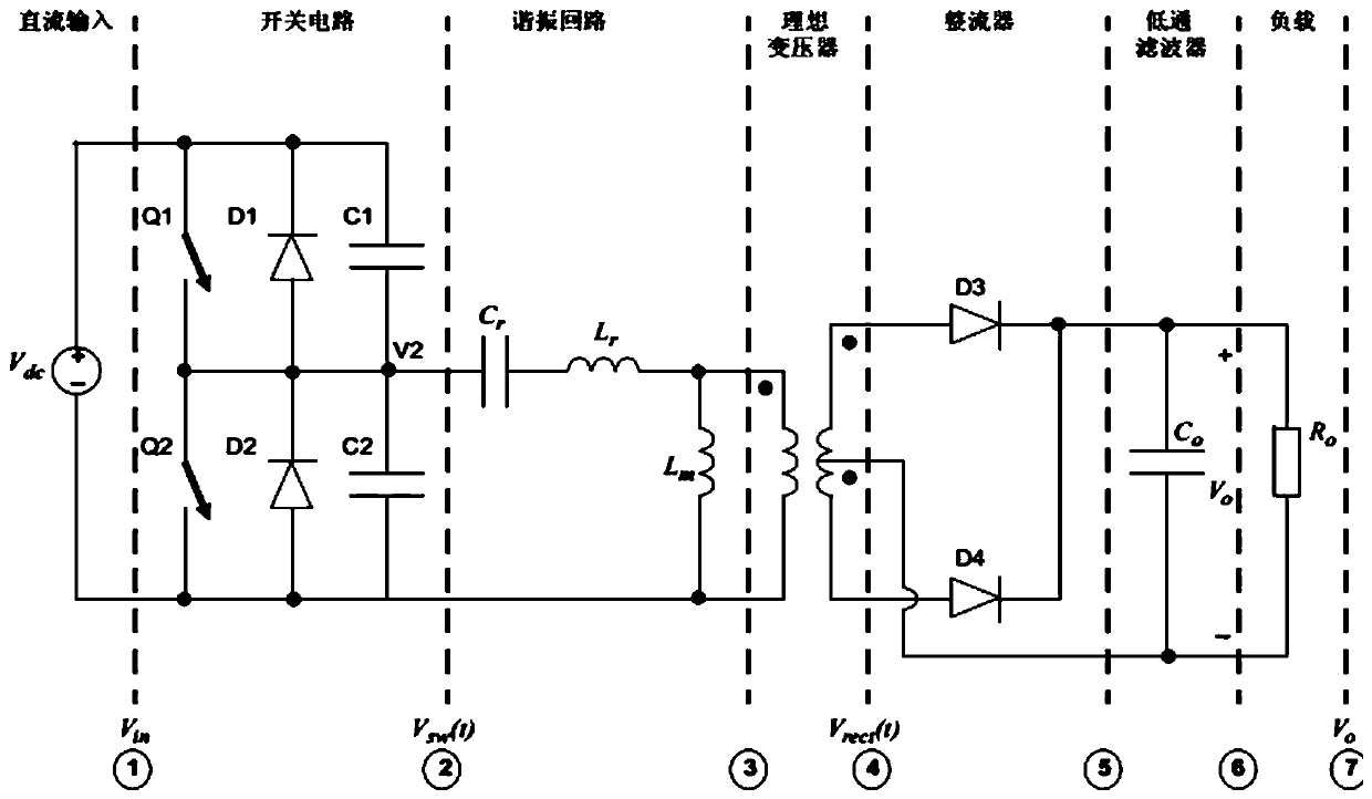
[0030] Such as figure 1 , 2 , 3, 4, 5, and 6, a step-down power supply circuit based on two-stage cascaded voltage conversion, including DC input voltage VIN, input voltage signal ground GND, output DC voltage VOUT, output voltage signal ground SGND, resistor Devices R1, R2, capacitors C1~C7, inductors L1, L2, MOS tubes Q1~Q6, microcontroller U1, MOS drivers U2~U6, transformers T1~T3; the model of the microcontroller U1 is dsPIC33FJ16GS502.

[0031] The DC input voltage VIN is connected to resistor R1, capacitor C1, capacitor C3 and one end of MOS transistor Q1; the other end of resistor R1 is connected to resistor R2, capacitor C1, capacitor C2, and the primary end of transformer T1; the other end of MOS transistor Q1 is connected to inductor One end of inductor L1 and MOS tube Q2...


PUM


Abstract

The invention relates to the technical field of power supplies and discloses a step-down power supply circuit and method based on two-stage cascaded voltage conversion. The step-down power supply circuit used by the method is a LLC+Buck two-stage cascaded topological circuit formed by connecting a source converter to a load converter through a filter, and includes a DC input voltage VIN, an inputvoltage signal ground GND, an output DC voltage VOUT, an output voltage signal ground SGND, resistors R1 and R2, capacitors C1 to C7, inductors L1 and L2, MOS transistors Q1 to Q6, single-chip microcomputer U1, MOS drivers U2 to U6, and transformers T1 to T3. The step-down power supply circuit and method aim to solve the low circuit efficiency and difficulty in selection of power devices such as MOSFETs in the case of a wide input voltage range.

Description

technical field [0001] The present invention relates to the technical field of power supply, in particular to a step-down power supply circuit and method based on two-stage cascaded voltage conversion. Background technique [0002] With the development of power electronics technology, switching power supplies tend to be more and more high-frequency. The volume weight of components such as transformers and inductors and capacitors decreases with the increase of switching frequency, so high frequency not only improves the power density of switching power supply, but also promotes the miniaturization of switching power supply. The classic Buck, Boost and isolated bridge circuits, flyback and forward converters can meet the normal applications in most systems. But in some special occasions, the usual single-stage power converter cannot meet the performance index. For example, some occasions that require high power factor power supply are usually composed of Boost PFC+Flyback c...

Claims


Application Information

Patent Timeline
Patent Type & Authority Applications(China)
IPC IPC(8): H02M3/158H02M3/335
Inventor 吴重重段庆锋张贯强
Owner LUOYANG LONGSHENG SCI & TECH
Learn More