
Eddy imaging based metal component defect quantitative detection method and device

A quantitative detection method and technology for metal components, applied in the direction of material magnetic variables, etc., can solve the problems of obvious defect transition area, low defect quantitative detection accuracy, and unsatisfactory imaging results, so as to simplify the processing steps and realize the quantitative detection of defect depth. Effect

Inactive Publication Date: 2019-05-31
UNIV OF ELECTRONICS SCI & TECH OF CHINA +1
View PDF6 Cites 11 Cited by
  • Summary
  • Abstract
  • Description
  • Claims
  • Application Information

AI Technical Summary

Problems solved by technology

However, these methods are based on the traditional eddy current testing method, the imaging results are not ideal, the defect transition area is obvious, only the approximate position and shape of the defect can be obtained, and the defect quantitative detection accuracy is not high

Method used


Image

  • Eddy imaging based metal component defect quantitative detection method and device
  • Eddy imaging based metal component defect quantitative detection method and device
  • Eddy imaging based metal component defect quantitative detection method and device

Examples


Embodiment Construction

[0030] In order to facilitate those skilled in the art to understand the technical content of the present invention, the content of the present invention will be further explained below in conjunction with the accompanying drawings.

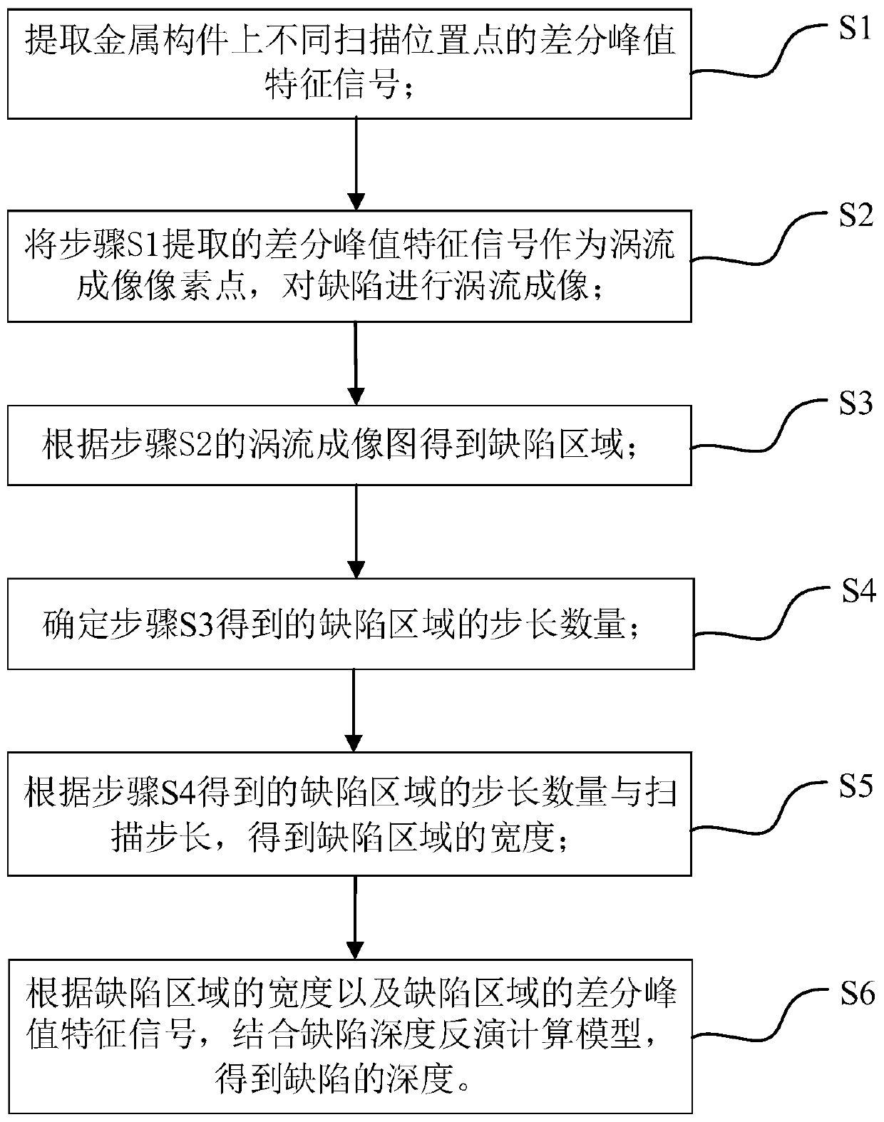
[0031] Such as figure 1 Shown is the scheme flow chart of the present invention, a metal member defect detection method based on eddy current imaging of the present invention, including:

[0032] S1. Extracting the differential peak characteristic signals of different scanning positions on the metal component;

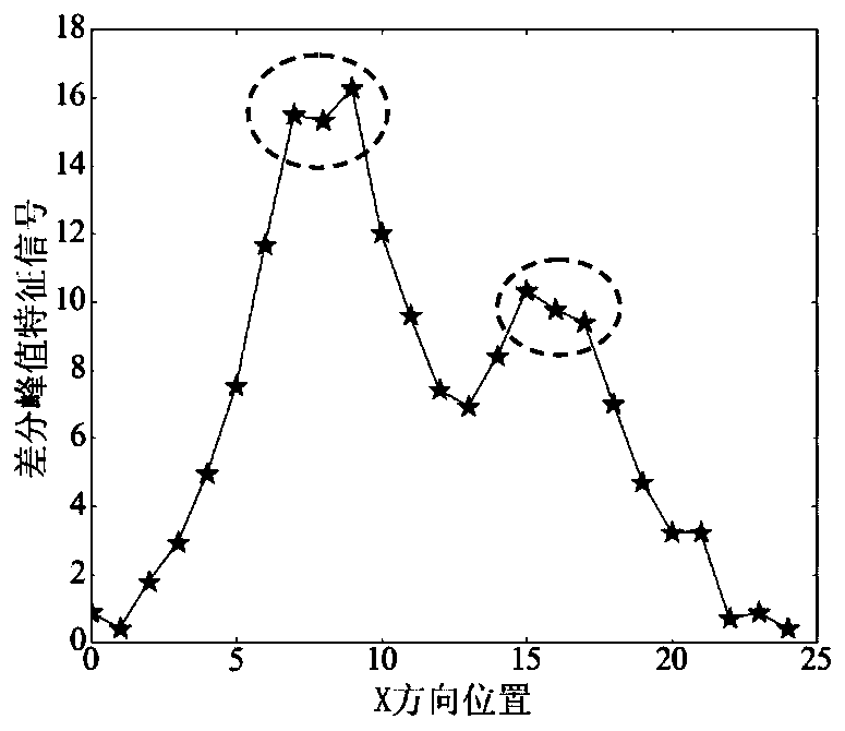
[0033] Based on pulsed eddy current detection technology, the differential peak characteristic signals on metal components at different scanning positions are extracted, that is, the maximum value extracted by differential processing between the magnetic field detection signal at each position point and the non-defective reference signal. The probe of the detection system device is placed on the non-defective area of ​​the test piece to ...


PUM


Abstract

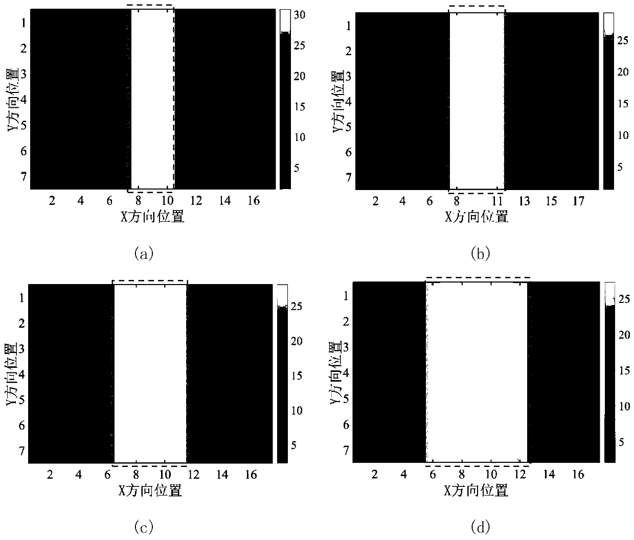
The invention discloses an eddy imaging based metal component defect quantitative detection method and device. Aiming at problems of failure in simultaneous quantitative detection of the position, width and depth of defects, serious noise interferences on characteristic signals and low accuracy in defect quantitative detection in existing eddy detection, the method includes steps: extracting difference peak characteristic signals of different scanning position points on a metal component; taking the extracted difference peak characteristic signals as eddy imaging pixels for eddy imaging of defects; acquiring defective areas according to obtained eddy images; determining step length quantity in the defective areas; acquiring widths of the defective areas according to scanned step lengths and the obtained step length quality in the defective areas; after determination of the defect widths, acquiring defect depths according to a defect depth back calculation module. The method and the device have the advantage that complex image processing techniques are avoided, so that processing steps are simplified.

Description

technical field [0001] The invention belongs to the field of non-destructive testing, in particular to a pulsed eddy current testing technology. Background technique [0002] Conventional nondestructive testing methods mainly include eddy current testing, magnetic particle testing, penetrant testing, ultrasonic testing, and ray testing. Compared with other non-destructive testing methods, the eddy current testing method based on the principle of electromagnetic induction can detect the surface and internal defects of the test piece at the same time, without coupling reagents, fast detection speed and high sensitivity. Therefore, domestic and foreign scholars have carried out a lot of research in this field. Research. Eddy current detection methods include single-frequency eddy current, multi-frequency eddy current, far-field eddy current, magneto-optical eddy current, pulsed eddy current detection, etc. Among them, the pulsed eddy current detection technology is widely use...

Claims


Application Information

Patent Timeline
Patent Type & Authority Applications(China)
IPC IPC(8): G01N27/90
Inventor 于亚婷薛珂王伟王聪王振伟杜平安聂宝林
Owner UNIV OF ELECTRONICS SCI & TECH OF CHINA
Learn More