
Inertial measurement module

A technology of inertial measurement and inertial components, which is applied in directions such as navigation through velocity/acceleration measurement, which can solve the problems affecting the accuracy of inertial measurement, high bias instability scale factor error of MEMS sensors, etc., to simplify the manufacturing process and achieve a compact structure. , to ensure the effect of electrical isolation

Active Publication Date: 2019-05-31
上海戴世智能科技有限公司
View PDF7 Cites 2 Cited by
  • Summary
  • Abstract
  • Description
  • Claims
  • Application Information

AI Technical Summary

Problems solved by technology

The disadvantage of this type of technical solution is that the MEMS sensor itself has high bias instability (Bias instability) and scaling factor error (Scaling error), both of which will be affected by temperature changes, and ultimately affect the accuracy of inertial measurement

Method used


Image

  • Inertial measurement module
  • Inertial measurement module
  • Inertial measurement module

Examples


Embodiment Construction

[0022] It is easy to understand that, according to the technical solution of the present invention, those skilled in the art can propose multiple structural modes and implementation modes that can be replaced without changing the essence and spirit of the present invention. Therefore, the following specific embodiments and drawings are only exemplary descriptions of the technical solution of the present invention, and should not be regarded as the entirety of the present invention or as a limitation or restriction on the technical solution of the present invention.

[0023] The directional terms such as up, down, left, right, front, back, front, back, top, and bottom that are mentioned or may be mentioned in this specification are defined relative to the structures shown in the drawings, and they are It is a relative concept, so it may change accordingly according to its different positions and different usage states. Accordingly, these or other directional terms should not be...


PUM


Abstract

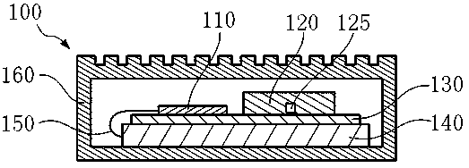
The present invention provides an inertial measurement module. The inertial measurement module (100) comprises a control unit (110), an inertial element (120), a temperature sensor (125), a substrate(130), a temperature control element (140) and a housing (160), and the control unit (110) monitors the temperature of the inertial element (120) through the temperature sensor (125) and controls thetemperature control element (140) to control the temperature of the inertial element (120). The control unit (110) and the inertial element (120) are installed at the same surface of the substrate (130), the temperature control element (140) is installed at the other surface of the substrate (130), and the temperature control element (140) is installed on the housing (160).

Description

technical field [0001] The invention relates to an inertial measurement module (IMU), in particular to the occasion of using a micro-electromechanical element (MEMS) as an inertial sensor. Background technique [0002] Inertial sensors are used to acquire acceleration and angular velocity. Currently there is a trend that more and more inertial measurement modules based on MEMS sensors are used, and patent CN104729505A discloses a similar technology. The disadvantage of this type of technical solution is that the MEMS sensor itself has high bias instability (Bias instability) and scaling factor error (Scaling error), both of which will be affected by temperature changes, which will eventually affect the accuracy of inertial measurement. Contents of the invention [0003] The object of the present invention is to propose an inertial measurement module, which improves the robustness to temperature changes, so that higher inertial measurement accuracy can be provided, and the...

Claims


Application Information

Patent Timeline
IPC IPC(8): G01C21/16
Inventor 陆海峰卞江
Owner 上海戴世智能科技有限公司
Learn More