Novel compressed air energy storage system

A technology of compressed air energy storage and storage system, which is applied in the direction of steam engine device, liquid variable displacement machinery, variable displacement pump components, etc. It can solve the problems of long external work time, pressure loss of pressure reducing valve, long sustainable time, etc. , to achieve the effect of reducing the difficulty of production technology, reducing the loss of pressure energy and improving the working ability

Inactive Publication Date: 2019-05-31
郭祚刚 +1
View PDF3 Cites 3 Cited by
  • Summary
  • Abstract
  • Description
  • Claims
  • Application Information

AI Technical Summary

Problems solved by technology

[0003] The existing compressed air energy storage technology has two defects. One is that the high-pressure air in the air storage space needs to be decompressed through the pressure reducing valve, resulting in a large loss of pressure energy. In the process of compressed air energy storage, In order to store as much compressed air as possible in the air storage space, the air is usually compressed to high pressure air (such as 8MPa or even higher pressure), the higher the pressure of the compressed air stored in the air storage air, the higher the pressure in the given air Under the condition of the inlet pressure of the expander, the longer the time for the air storage space to release compressed air stably, the longer the time for the corresponding air expander to output electric energy; if the compressed air pressure in the air storage space is 5Mpa, the first air The design pressure at the inlet of the expander is 4.6MPa. If the pressure in the air storage space drops to 4.6MPa in a short time, the air expander cannot work. If the compressed air pressure in the air storage space is set to 8MPa, the air in the air storage space will The sustainable time before the pressure drops to 4.6MPa is longer
Therefore, in order to make the compressed air energy storage system have a longer external work time, the air storage space is usually stored at a compressed air pressure that is much higher than the design pressure of the air expander inlet, forming a pressure difference. The existing technology The pressure reduction and stabilization of 8MPa to 4.6MPa is directly realized through the pressure reducing valve, and the pressure of 3.4MPa is lost, so that the ability of the compressed air energy storage system to output electric energy is lost. Therefore, the existing compressed air energy storage systems all exist Large pressure loss caused by pressure relief valve
[0004] The second is that the compressed air in the air storage space enters the air expander to do work at a relatively low temperature, and there is no effective way to increase the temperature of the air entering the air expander. In the case of no supplementary combustion, the air expander of the existing compressed air energy storage system The air temperature at the inlet is usually relatively low. For the non-supplementary combustion compressed air energy storage technology, the temperature of the outlet air of the air compressor in the energy storage stage is generally lower than 160 degrees in the absence of external heat sources, so that the compressed air energy storage system Part of the heat of compression heats the inlet airflow of the air expander in the working stage, so that the temperature of the airflow at the inlet of the air expander is lower than 150 degrees. The lower inlet temperature reduces the ability of the airflow to do work outside the air expander. In addition, the existing Supplementary combustion compressed air energy storage technology lacks burners suitable for combustion under high pressure, and there is no production capacity of high-pressure burners in China, which also limits the efficiency of compressed air energy storage systems
Therefore, the above two defects reduce the efficiency of compressed air energy storage technology

Method used


Image

  • Novel compressed air energy storage system
  • Novel compressed air energy storage system
  • Novel compressed air energy storage system

Examples


Embodiment 1

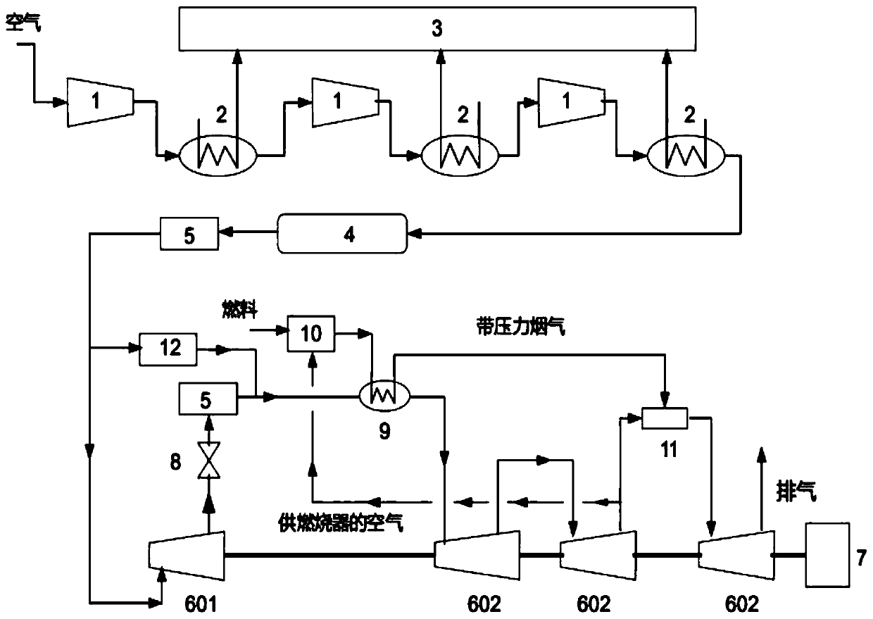
[0040] This embodiment can be used not only in the peak-shaving and valley-filling scenarios of the power grid, but also in the large-scale storage and release of new energy such as photovoltaic power generation or wind power. see figure 1 , the electric energy storage process, the electric energy is used to drive the multi-stage air compression unit 1 to do work to prepare high-pressure compressed air, store the high-pressure compressed air in the air storage space 4, and the compressed air discharged from the air compression unit 1 passes through the heat exchanger 1 and 2 for cooling, and then enter the next air compression unit 1 to compress to further increase the pressure of the output air. After being pressurized by multiple air compression units 1, the air can be compressed from the normal pressure state to the required high pressure state . During the preparation process of high-pressure air, the heat exchanger 12 transfers the heat carried by the air to the heat exc...

Embodiment 2

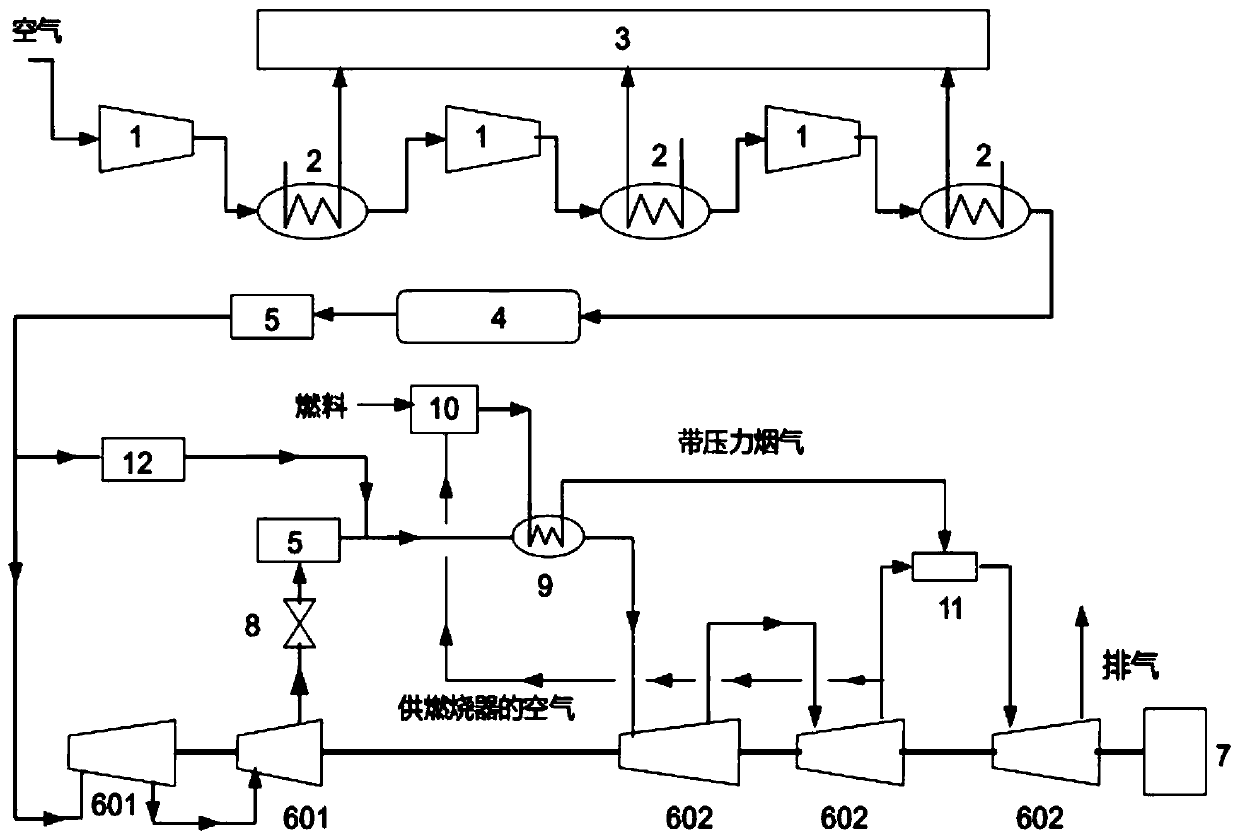
[0049] This embodiment can be used not only in the peak-shaving and valley-filling scenarios of the power grid, but also in the large-scale storage and release of new energy such as photovoltaic power generation or wind power. see figure 2 , the difference from Embodiment 1 is that two first expansion units 601 are arranged before the back pressure valve 8, and the pressurized air required for combustion of the burner 10 comes from the pressurized exhaust gas of the second second expansion unit 602.

[0050] The back pressure valve 8 is set at the exhaust port of the second first expansion unit 601, so that the first expansion unit 601 has the sliding pressure operation ability to adapt to the real-time drop of the air pressure in the air storage space 4, and also maintains the second first expansion unit 601. The stability of the exhaust pressure of the expansion unit 601 allows the first, second and third second expansion units 602 connected after the back pressure valve 8 ...

Embodiment 3

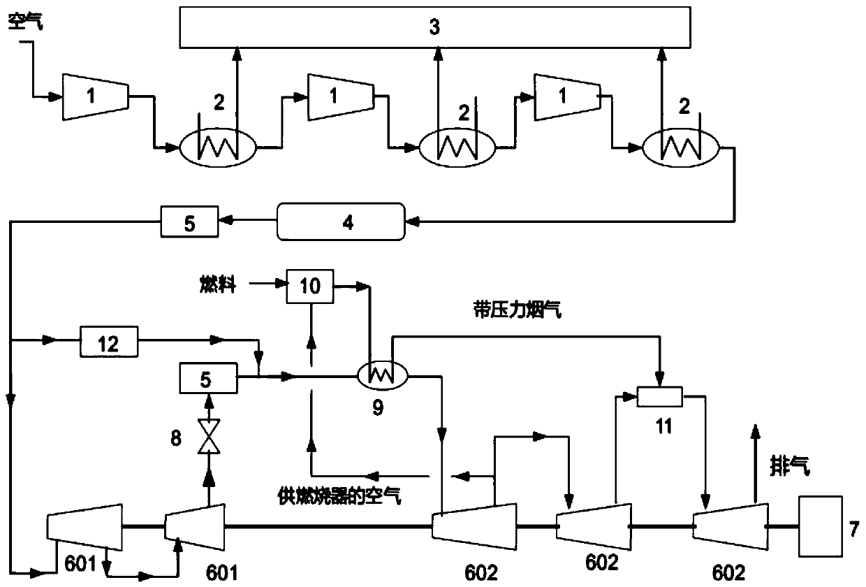
[0052] This embodiment can be used not only in the peak-shaving and valley-filling scenarios of the power grid, but also in the large-scale storage and release of new energy such as photovoltaic power generation or wind power. see image 3 , and the difference from the second embodiment, the combustion air required by the burner 10 is exhausted from the first and second expansion units 602 .

[0053] The back pressure valve 8 is set at the exhaust port of the second first expansion unit 601, so that the first and second first expansion unit 601 have the sliding pressure operation ability to adapt to the real-time drop of the air pressure in the gas storage space 4, and at the same time The stability of the exhaust pressure of the second first expansion unit 601 is maintained, so that the first, second and third second expansion units 602 connected after the back pressure valve 8 can all operate at the set stable pressure parameters to run.


PUM


Abstract

The invention discloses a novel compressed air energy storage system comprising an electric energy storage system and an electric energy release system. The electric energy storage system comprises aplurality of air compression units, a plurality of heat exchangers I, a heat storage tank and an air storage space, and the electric energy release system comprises a first expansion unit system, a second expansion unit system and a burner system; and the first expansion unit system comprises a plurality of first expansion units and a back pressure valve, and the second expansion unit system comprises a plurality of second expansion units, a plurality of heat exchangers II, an energy storage system waste heat recycling heat exchanger, a pressure reducing valve, a gas mixing device and a generator. According to the novel compressed air energy storage system, the first expansion unit system is provided with the back pressure valve so that the first expansion unit system has the ability of sliding pressure operation; an external burner is provided for proper afterburning through the second expansion units by using pressurized exhaust as supply air, and the performance ability of compressed air flow is improved; the gas mixing device is provided, so that reutilization of waste pressure and waste heat of burner flue gas is achieved; and the system efficiency is improved greatly.

Description

technical field [0001] The invention relates to the field of electric energy storage, and is specifically used for large-scale storage of power grid electric energy to realize peak-shaving and valley-filling of power grid loads, and can also be used for quality improvement of new energy power such as solar power generation technology or wind power generation technology and large-scale storage of electric energy A new type of compressed air energy storage system. Background technique [0002] Compressed air energy storage technology is a large-scale physical energy storage technology. When the power grid is in a low load period, the cheap electric energy during the valley period is used to drive the air compressor to do work, and the cheap low-valley electric energy is converted into the pressure energy of compressed air for storage. When the power grid is at the peak of power consumption, the high-pressure compressed air in the gas storage space is released. After the temper...

Claims


Application Information

Patent Timeline
Patent Type & Authority Applications(China)
IPC IPC(8): F04B41/06F04B41/02F04B39/06F01K7/22F01K7/10F01K7/38
CPCY02E60/16
Inventor 郭祚刚翟晓慧
Owner 郭祚刚
Why Eureka
Try Eureka