A kind of manufacturing method of high radioactive waste vitrified body storage tank

A glass-curing, highly radioactive technology, used in manufacturing tools, hollow objects, forming tools, etc., to ensure tightening torque, prevent screw loosening, and reduce maintenance frequency

Active Publication Date: 2020-04-28
成都纵远机械设备有限公司
View PDF10 Cites 0 Cited by
  • Summary
  • Abstract
  • Description
  • Claims
  • Application Information

AI Technical Summary

Problems solved by technology

[0007] The purpose of the present invention is to: provide a kind of manufacturing method of high radioactive waste vitrified body storage tank, solve the problem that the bottom of the punch used for each stretching in the existing drawing die all protrudes into a spherical surface, causing the tank body The problem that the bottom is getting thinner and thinner

Method used


Image

  • A kind of manufacturing method of high radioactive waste vitrified body storage tank
  • A kind of manufacturing method of high radioactive waste vitrified body storage tank
  • A kind of manufacturing method of high radioactive waste vitrified body storage tank

Examples


Embodiment 1

[0044] A method for manufacturing a vitrified body storage tank for high-level radioactive waste, comprising the steps of:

[0045] S1. Place the plate used to manufacture the storage tank on the die assembly of the bottom drawing die, then start the driving cylinder of the punch assembly of the bottom draw die, press down the punch assembly, and press the plate The middle part is drawn deep into the forming cavity of the die assembly to form a preliminary finished tank body with a tank bottom;

[0046] S2. The finished product of the preliminary tank body is removed from the die assembly of the bottom drawing die, and placed on the die assembly of the first drawing die, and then the driving of the punch assembly of the first drawing die is started Cylinder, press down the punch assembly, and continue to draw the side wall of the tank body formed by the middle part of the plate, so as to form a primary tank body product with a certain depth;

[0047] S3, take off the primary ...

Embodiment 2

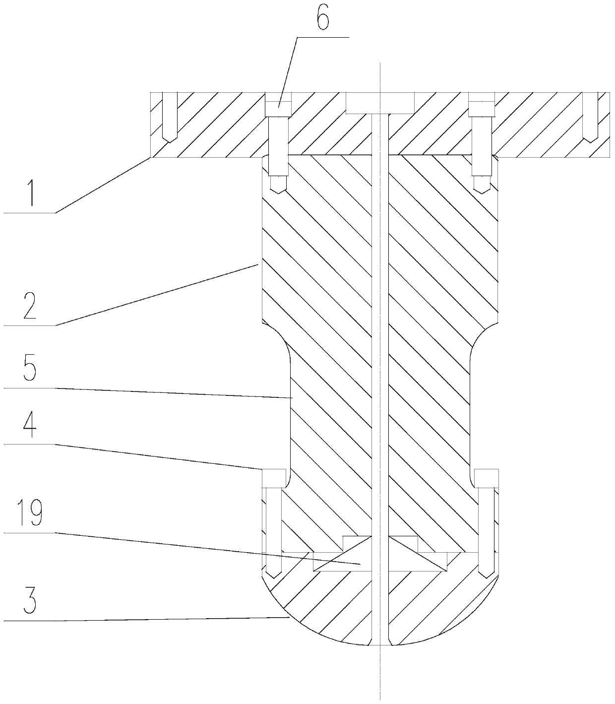
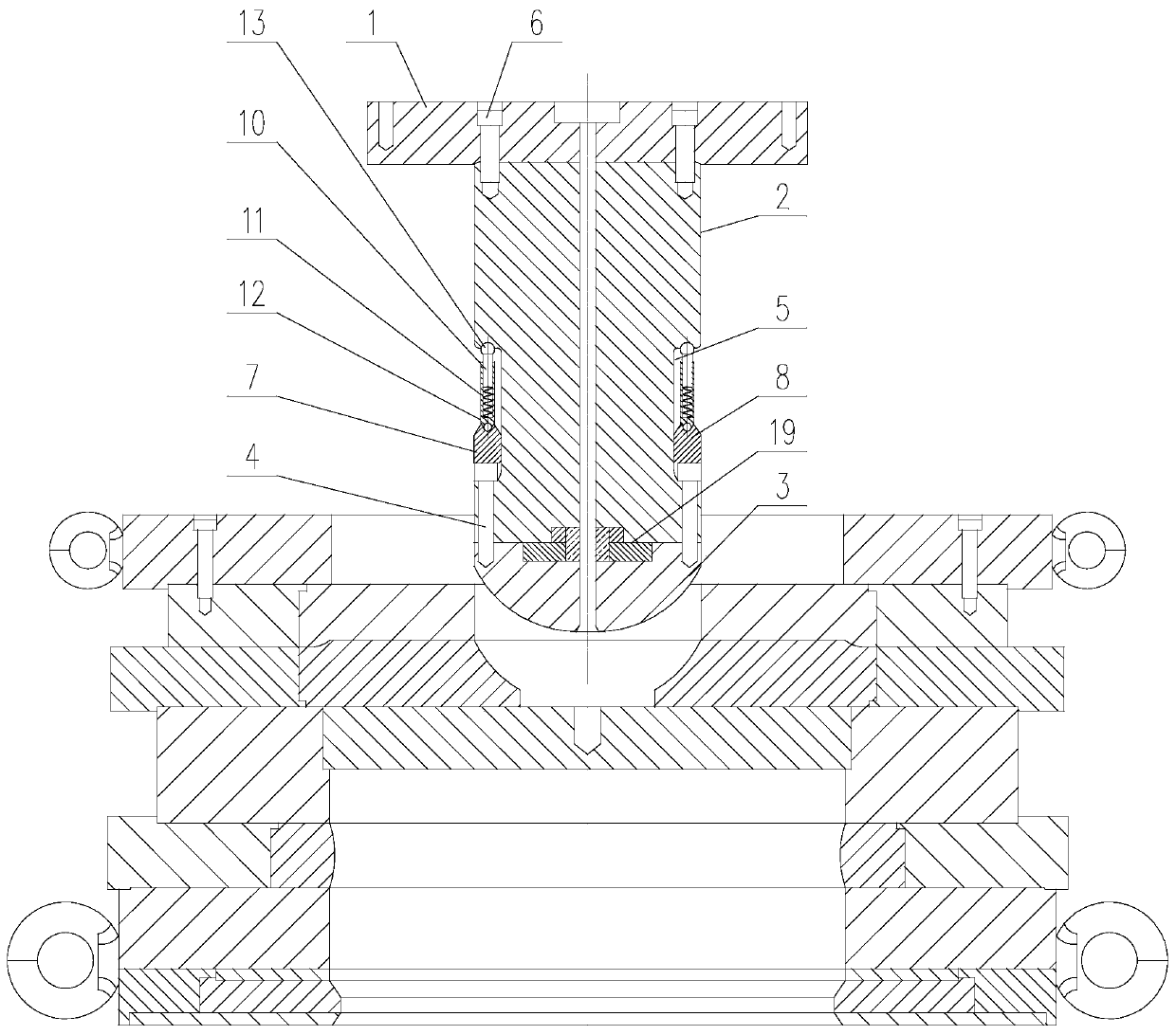
[0052] Such as Figure 2-Figure 4 As shown, the present invention is a kind of manufacturing equipment for the storage container of vitrified body, which includes a deep drawing die, and the deep drawing die includes a male mold assembly and a female mold assembly located below the male mold assembly, and the male mold The assembly includes a coaxial extension die 2 and a punch 3 connected by a screw A4, and an annular groove A5 coaxial with the extension die 2 is provided on the side wall of the extension die 2, and the ends of the rods of the screws A4 pass through in turn. After passing through the lower side groove wall of the annular groove A5 and the extension die 2, it is threadedly connected with the punch 3, and the end of the extension die 2 far away from the punch 3 is connected with the punch base 1 through a screw B6, and is set on the extension die 2. A tightening assembly is provided, and the tightening assembly includes a ring 7, an elastic telescopic rod and a...

Embodiment 3

[0061] This embodiment is an implementation description of the first specific implementation structure of the telescopic rod.

[0062] Such as Figure 2-Figure 3 As shown, in the present invention, the telescopic rod includes a moving rod 10, a spring 11 and a mounting cylinder 12 connected in sequence, the top end of the moving rod 10 is in contact with the upper groove wall of the annular groove A5, and the bottom end is inserted into the mounting cylinder 12, and contact with the bottom of the installation cylinder 12 through the spring 11, and the spring 11 is in a compressed state, the bottom of the installation cylinder 12 is connected with the upper surface of the ring 7.


PUM


Abstract

The invention discloses a manufacturing method of a high-level radioactive waste glass solidified body storage tank; the manufacturing method of the high-level radioactive waste glass solidified bodystorage tank comprises the following steps of: S1, drawing the middle part of a plate to a forming cavity of a female die assembly to form a preliminary tank body finished product with a tank body bottom; S2, continuously drawing the side wall of the tank body formed in the middle part of the plate to form the preliminary tank body finished product with a certain depth; S3, continuously drawing the side wall of the tank body formed in the middle part of the plate to form an intermediate tank body finished product with an increased depth; S4, continuously drawing the side wall of the tank bodyformed in the middle part of the plate to form a final tank body finished product; In the invention, apart from the first use of a convex die which is convexly formed into a spherical surface when thebottom of the tank body is stretched; in the subsequent several times of stretching, the convex die whose inner bottom is concavely formed into the concave spherical surface is used to ensure the thickness of the bottom of the tank body and the strength of the tank body.

Description

technical field [0001] The invention relates to the field of deep-drawing molds, in particular to a method for manufacturing a high-radioactive waste vitrified body storage tank. Background technique [0002] Highly radioactive waste is usually disposed of through the vitrification process. Vitrification is the process of mixing waste into a glass base to form a vitrified body. The vitrification process involves concentrating and calcining radioactive waste to convert the salt contained in it into oxides, and then melting it with the glass base material, and finally casting it into a vitrified body. [0003] Tanks are often used as storage containers for vitrified high-level waste. In order to ensure the high quality of the tanks used to store high-level waste vitrified bodies, the tanks are mainly manufactured by stretching. The stretching process draws the plate into a cylindrical shape with an open top, and then seals the top of the cylindrical structure by welding or ...

Claims


Application Information

Patent Timeline
Patent Type & Authority Patents(China)
IPC IPC(8): B21D37/10B21D51/18B21D37/04
Inventor 刘俊安继兰
Owner 成都纵远机械设备有限公司
Why Eureka
Try Eureka