Optical microscopic imaging method and device for online monitoring in high temperature state

A high-temperature state, optical microscopy technology, applied in measurement devices, optics, microscopes, etc., can solve problems such as the close distance between the microscope and the heat source, and the system is complex, achieving adjustable test environment, large imaging working distance, and wide temperature measurement range. Effect

Active Publication Date: 2019-05-28
NORTHWEST INST OF NUCLEAR TECH
View PDF8 Cites 0 Cited by
  • Summary
  • Abstract
  • Description
  • Claims
  • Application Information

AI Technical Summary

Problems solved by technology

[0005] In order to solve the problems of the existing high-resolution dynamic optical microscopic imaging scheme, such as complex system and short distance between the microscope and the heat source, the present invention proposes a new optical microscopic imaging method and device for on-line monitoring under high temperature conditions

Method used


Image

  • Optical microscopic imaging method and device for online monitoring in high temperature state
  • Optical microscopic imaging method and device for online monitoring in high temperature state

Examples


Embodiment 1

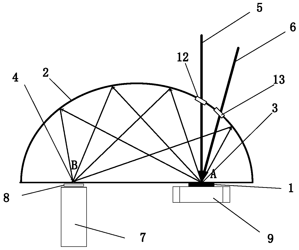
[0031] see figure 1 , the sample 1 is placed at the focal point A of the conjugate imaging surface 2, and the optical microscope 7 is placed at the focal point B; the sample is installed on the position adjustment mechanism 9, which can realize the adjustment of the position of the sample in the three-dimensional direction, ensuring that the measured The center of the area is always on focus A. The sample 1 is heated by the laser 6 to achieve a high temperature state; the laser light source is located outside the conjugate imaging plane, and the heating laser 6 enters through the light window 13 to heat the sample 1 . The illumination light 5 irradiates the surface of the sample 1 through the light window 12 and forms an image at the focal point B. A filter 8 is installed in front of the optical microscope to filter out laser signals to eliminate interference to imaging. Use an optical microscope to magnify the conjugate image to obtain a microscopic image.

Embodiment 2

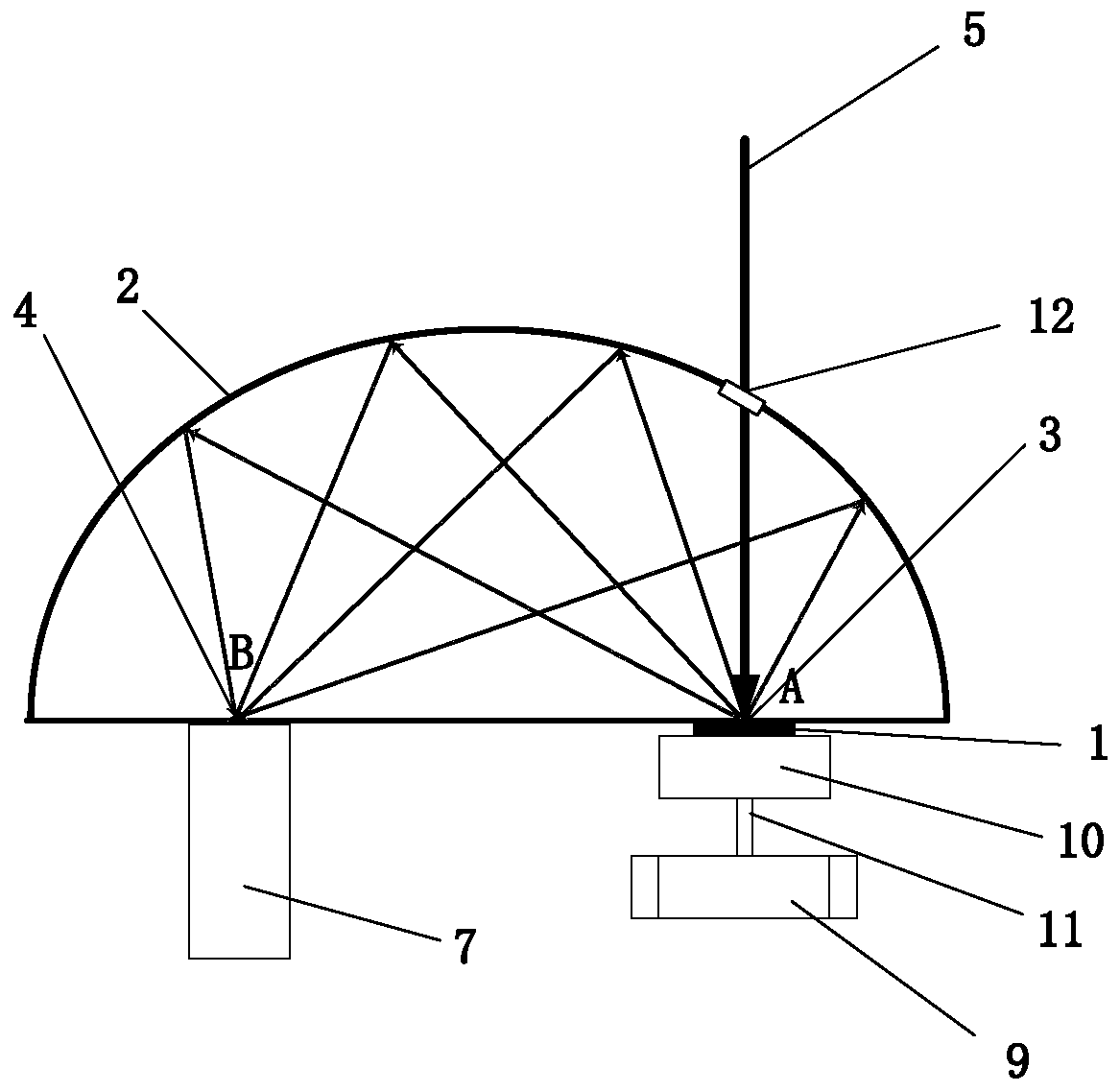
[0033] see figure 1 , the sample 1 is placed at the focal point A of the conjugate imaging surface 2, and the optical microscope 7 is placed at the focal point B; the sample is installed on the position adjustment mechanism 9, which can realize the adjustment of the position of the sample in the three-dimensional direction, ensuring that the measured The center of the area is always on focus A. A heater 10 is arranged on the back of the sample to realize a high temperature state; a heat insulation assembly 11 is arranged between the heater 10 and the position adjustment mechanism 9 . The illumination light 5 irradiates the surface of the sample 1 through the light window 12 and forms an image at the focal point B. Use an optical microscope to magnify the conjugate image to obtain a microscopic image.


PUM


Abstract

The invention provides an optical microscopic imaging method and device for online monitoring in a high temperature state. The method and device aim at solving the problems that in an existing high-resolution dynamic optical microscopic imaging scheme, a system is complicated, and the distance between a microscope and a heat source is short. The method comprises the following steps of 1) placing asample and an optical microscope on a focus A and a focus B of a conjugate imaging surface respectively; 2) heating the sample and maintaining the high temperature state; 3) illuminating the surfaceof the sample by illumination light to generate diffuse reflection, then conducting reflection through the conjugate imaging surface, and receiving a conjugate image by the optical microscope for amplification to obtain a microscopic image; 4) if different areas on the surface of the sample need to be observed, moving the sample, ensuring that the center of each tested area is always at the focusA, and obtaining a microscopic image according to the third step.

Description

technical field [0001] The invention belongs to the field of optical microscopic analysis, and relates to an online optical microscopic imaging method and device. Background technique [0002] Microscope, as one of the greatest inventions in human history, has a very wide range of applications in many fields such as life medicine, biological science, and materials science. Using microscope and microscopic imaging technology, it is convenient to observe the structure and morphology of cells, tissue, surface micro-topography of materials / devices, and monitor changes inside cells in real time. Microscopes are mainly divided into two categories: optical microscopes and electron microscopes. Electron microscopes have the unparalleled high resolution of optical microscopes, but they have high requirements on the working environment and it is difficult to achieve non-destructive observation. Relatively speaking, optical microscopes are cheap and easy to operate, but the disadvant...

Claims


Application Information

Patent Timeline
Patent Type & Authority Applications(China)
IPC IPC(8): G02B21/36G02B21/30G02B21/00G01N21/84
Inventor 吴丽雄冯国斌张检民陈绍武
Owner NORTHWEST INST OF NUCLEAR TECH
Why Eureka
Try Eureka