
Energy-saving cooking range

An energy-saving, stove technology, applied in the field of stoves, can solve the problems of stoves being unusable, lost, and flue gas transmission pipes are easily corroded and broken, and achieve the effects of simple structure, accurate installation position, and convenient operation

Pending Publication Date: 2019-05-28
JIANGSU SHENGONG STOVE CO LTD
View PDF0 Cites 0 Cited by
  • Summary
  • Abstract
  • Description
  • Claims
  • Application Information

AI Technical Summary

Problems solved by technology

Some stoves in the existing market have been improved, and the water body is heated through the recovery of heat energy to generate a large amount of steam for use in other processes, which improves energy utilization. However, due to the large amount of corrosive components in the flue gas, the flue gas The transmission pipe is easily corroded and broken. In the prior art, the flue gas transmission pipe is welded to the furnace body. Once the flue gas transmission pipe breaks, the entire furnace cannot be used and the loss is serious.

Method used


Image

  • Energy-saving cooking range
  • Energy-saving cooking range
  • Energy-saving cooking range

Examples


Embodiment Construction

[0018] The present invention will be described in detail in conjunction with accompanying drawing now. This figure is a simplified schematic diagram only illustrating the basic structure of the present invention in a schematic manner, so it only shows the components relevant to the present invention.

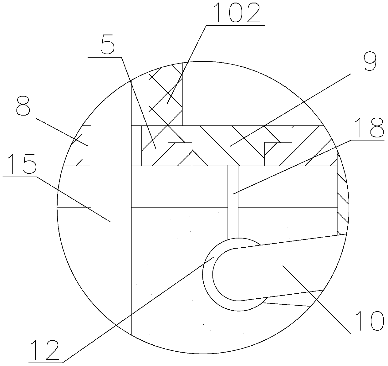
[0019] like Figure 1-6 As shown, an energy-saving stove of the present invention includes a hearth 1, a furnace body 2 and a water tank 3. The furnace body 2 is composed of an inner furnace wall 202 and an outer furnace wall 201. The back side of the outer furnace wall 201 is The back plate is detachably installed, the hollow area surrounded by the inner furnace wall 202 is the furnace 4, the inner furnace wall 202 and the outer furnace wall 201 are welded with a support plate 5, the inner furnace wall 202, the outer furnace wall The cavity formed between 201 and the support plate 5 is the heating cavity 6,

[0020] The support plate 5 is provided with an annular stepped hole...


PUM


Abstract

The invention provides an energy-saving cooking range. The energy-saving cooking range comprises a coil base, a furnace body and a water tank; supporting plates are connected to the upper ends of internal furnace walls and external furnace walls; cavities formed among the internal furnace walls, the external furnace walls and the supporting plates are heating cavity; annular holes and through holes are formed in the supporting plates; the through holes are formed in the external sides of the annular holes; the annular holes are of structures which are big at the upper parts and small at the lower parts; connecting plates matched with the annular holes are arranged in the annular holes; coiled pipes surrounding a hearth are arranged in the heating cavities; the coiled pipes are arranged under the connecting plates; the upper ends of the coiled pipes communicate with the hearth through connecting pipes; the lower ends of the coiled pipes vertically arranged downwards to penetrate throughthe bottom of the coil base to extend outwards; a plurality of lifting rings sleeve the coiled pipes; connecting rods are arranged between the lifting rings and the connecting plates; and the coil base is arranged at the upper end of the furnace body. According to the energy-saving cooking range, by using the connecting plates to lift the coiled pipes, the accurate mounting positions of the coiled pipes are guaranteed; the coiled pipes can be detached to be quickly changed by directly taking out the connecting plates upwards when the coiled pipes need to be repaired or changed; the structureis simple; and the operation is convenient and fast.

Description

technical field [0001] The invention relates to the technical field of stoves, in particular to an energy-saving stove. Background technique [0002] The heating principle of the stove is to heat the bottom of the pot by directly burning fuel through the atmosphere. Some stoves in the existing market have been improved, and the water body is heated through the recovery of heat energy to generate a large amount of steam for use in other processes, which improves energy utilization. However, due to the large amount of corrosive components in the flue gas, the flue gas The transmission pipe is easily corroded and broken. In the prior art, the flue gas transmission pipe is welded to the furnace body. Once the flue gas transmission pipe breaks, the entire furnace cannot be used and the loss is serious. Contents of the invention [0003] The technical problem to be solved by the invention is: in order to overcome the deficiencies in the prior art, the invention provides an ener...

Claims


Application Information

Patent Timeline
Patent Type & Authority Applications(China)
IPC IPC(8): F24C13/00F22B33/18
CPCY02B40/00
Inventor 顾加荣顾杨顾加华
Owner JIANGSU SHENGONG STOVE CO LTD
Learn More