A valve seat and a spiral oblique entry nozzle

A technology of valve seat and spiral groove, which is applied in the direction of fuel injection device, charging system, machine/engine, etc. It can solve the problems of affecting the spray effect and clogging the nozzle hole, etc., and achieves good results

Active Publication Date: 2019-07-16
常州江苏大学工程技术研究院 +1
View PDF6 Cites 0 Cited by
  • Summary
  • Abstract
  • Description
  • Claims
  • Application Information

AI Technical Summary

Problems solved by technology

However, in practice, after the nozzle has been used for a long time, some oil will remain on the inverted cone surface or spherical arc surface structure below the ball after the sphere is in contact with the inverted cone surface or spherical arc surface structure, which is easy to form a large amount of oil. Insoluble and interconnected polymeric network viscous substances, which gradually accumulate and finally adhere to the inverted cone surface or spherical arc surface structure, forming surface coking, and eventually blocking or partially blocking the nozzle hole, affecting the spray effect

Method used


Image

  • A valve seat and a spiral oblique entry nozzle
  • A valve seat and a spiral oblique entry nozzle
  • A valve seat and a spiral oblique entry nozzle

Examples


Embodiment 1

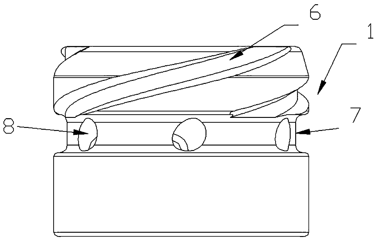
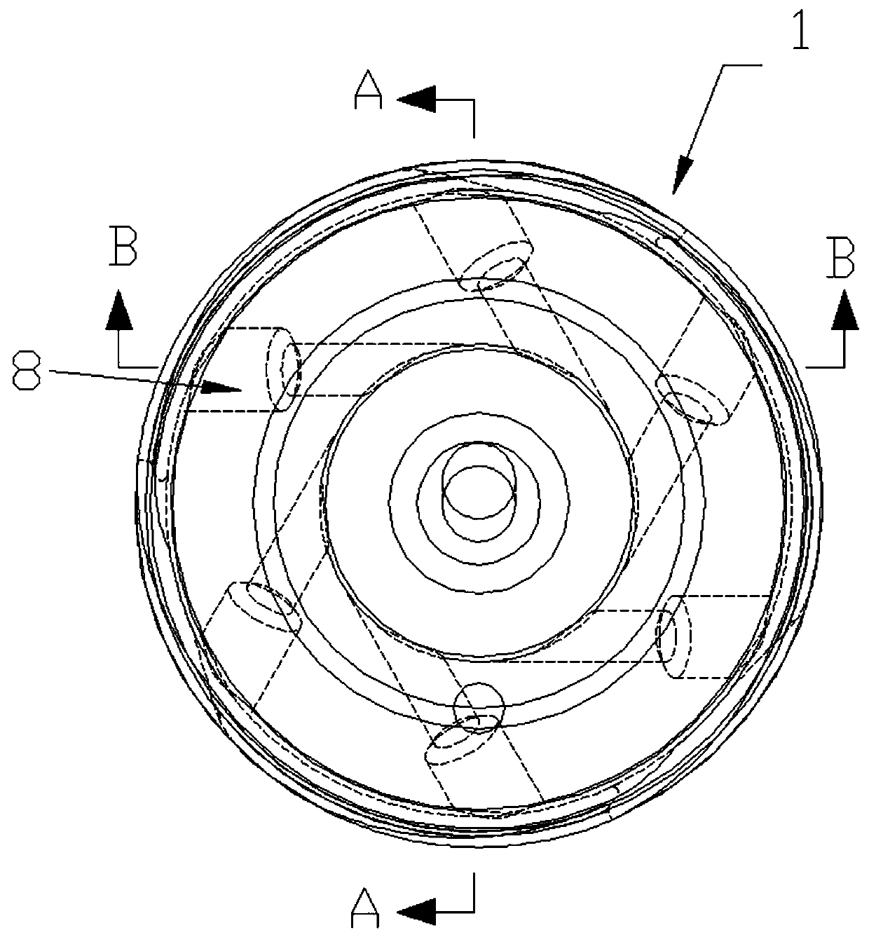
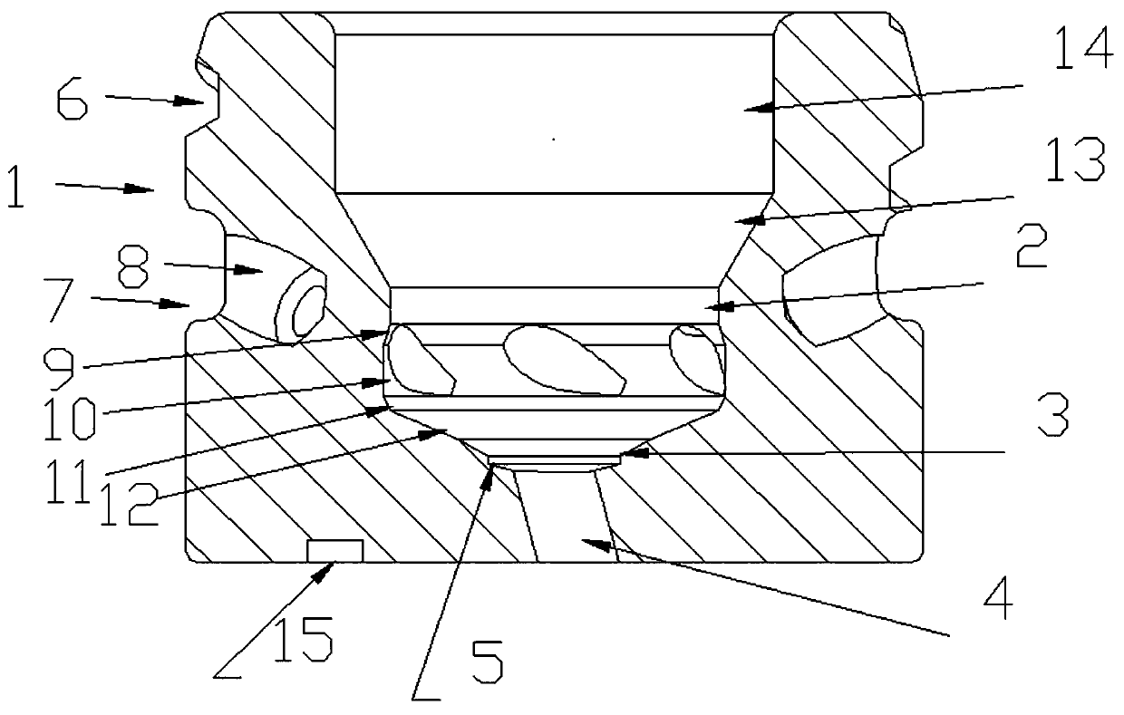
[0032] Such as Figure 1-5As shown, this embodiment discloses a valve seat, which includes: a valve seat body 1, the shape of the valve seat body 1 is not limited, as long as it can cooperate with the structure of the nozzle to realize the function of the nozzle, such as the oil pipe body , in this embodiment, the valve seat body 1 is preferably a cylindrical structure, more preferably a cylinder; the valve seat body 1 is provided with a first cylindrical cavity 2, a swirl cavity, and a first sealing cavity that communicate with each other. 3 and the nozzle hole 4. During use, the first cylindrical cavity 2 is in sliding contact with the sphere as much as possible to ensure that the valve core does not skew when the sphere slides. The swirl cavity is set on the first cylindrical cavity The shape of the bottom of the cavity 2 is not specifically limited, and it can be a regular shape or an irregular shape, such as a cylindrical cavity, a spherical cavity (non-integral), a frust...

Embodiment 2

[0036] Such as Image 6 with Figure 7 As shown, the present embodiment discloses a spiral inclined-in nozzle, which includes an oil pipe body 18, and the lower end of the oil pipe body 18 is socketed with the outer surface of the valve seat body 1 of the valve seat, so that the fluid flows in the spiral The groove 6 and the diversion groove 7 combine with the inner wall of the lower end of the oil pipe body 18 to form a closed fluid channel. After the fluid enters through the upper end of the spiral groove 6, the fluid has more impact and stability when rotating and flowing. The valve seat is the valve seat structure in Embodiment 1; it also includes a valve core 16, and the lower end of the valve core 16 is connected with a ball 17, and the ball 17 can be an existing ball of any shape, which can be a whole ball or a ball. It may be a partial sphere, and the sphere 17 cooperates with the first sealed cavity 3 to realize the spraying of the nozzle.

[0037] In addition, othe...


PUM


Abstract

The invention discloses a valve seat. A vacuum groove is formed on the wall of the first sealed cavity close to the nozzle hole. By setting the vacuum groove, the high-speed fluid medium rotates along the wall of the first sealed cavity and flows to the When the nozzle hole is described, the high-speed fluid medium drives the air in the vacuum tank to form a cyclone, thereby forming a negative pressure state, and in the process of forming the cyclone, the air enters the nozzle hole together with the fluid medium, and finally forms a mist spray. During this process, the cyclone disturbance of the air in the vacuum tank can take away the remaining part of the fluid medium on the part of the inverted cone surface or the spherical arc surface structure under the sphere after the sphere contacts and seals the inverted cone surface or the spherical arc surface structure, In this way, the residual fluid medium is avoided, and the impurities are hardened and dried to block the nozzle hole and affect the atomization effect.

Description

technical field [0001] The invention relates to the technical field of nozzles, in particular to a valve seat and a spiral inclined-in nozzle using the valve seat. Background technique [0002] The nozzle is one of the key parts of the EFI engine, its work will seriously affect the performance of the engine. Existing nozzles generally have a simple electromagnetic valve structure. For example, CN2016209634863 discloses a urea nozzle, which includes a housing, a valve body is provided in the housing, and a coil assembly is provided between the valve body and the housing. An adjustment sleeve and a valve core are provided in the valve body, and the valve core can slide in the valve body. A spring fixing seat is provided in the adjustment sleeve, and an elastic member is arranged between the spring fixing seat and the valve core. The front end of the spool passes through a sphere between the partition and the nozzle. The sphere is a whole sphere or a part of the sphere. There ...

Claims


Application Information

Patent Timeline
Patent Type & Authority Patents(China)
IPC IPC(8): F02M61/18
Inventor 刘新冬赵典秋袁亚飞庞贺臣刘劝
Owner 常州江苏大学工程技术研究院
Why Eureka
Try Eureka