
Die device for achieving drawing flanging forming

A flanging forming and mold technology, applied in the field of stamping molds, can solve the problems of stacking and wrinkling of process parts, and achieve the effect of simple structure, practical and reliable, and avoidance of wrinkling.

Inactive Publication Date: 2019-05-28
天津世亚模具股份有限公司
View PDF0 Cites 1 Cited by
  • Summary
  • Abstract
  • Description
  • Claims
  • Application Information

AI Technical Summary

Problems solved by technology

Since the process parts are always moving downstream during the flanging forming process, and the inflow speed remains unchanged, the process parts are prone to wrinkling and stacking during the forming process

Method used


Image

  • Die device for achieving drawing flanging forming
  • Die device for achieving drawing flanging forming
  • Die device for achieving drawing flanging forming

Examples


Embodiment Construction

[0015] Below in conjunction with the examples, the present invention is further described, the following examples are illustrative, not limiting, and the protection scope of the present invention cannot be limited by the following examples.

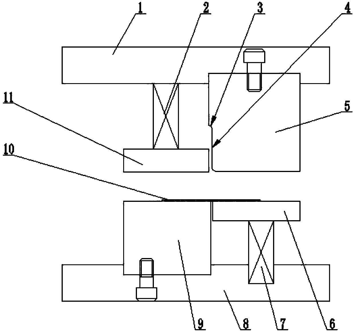
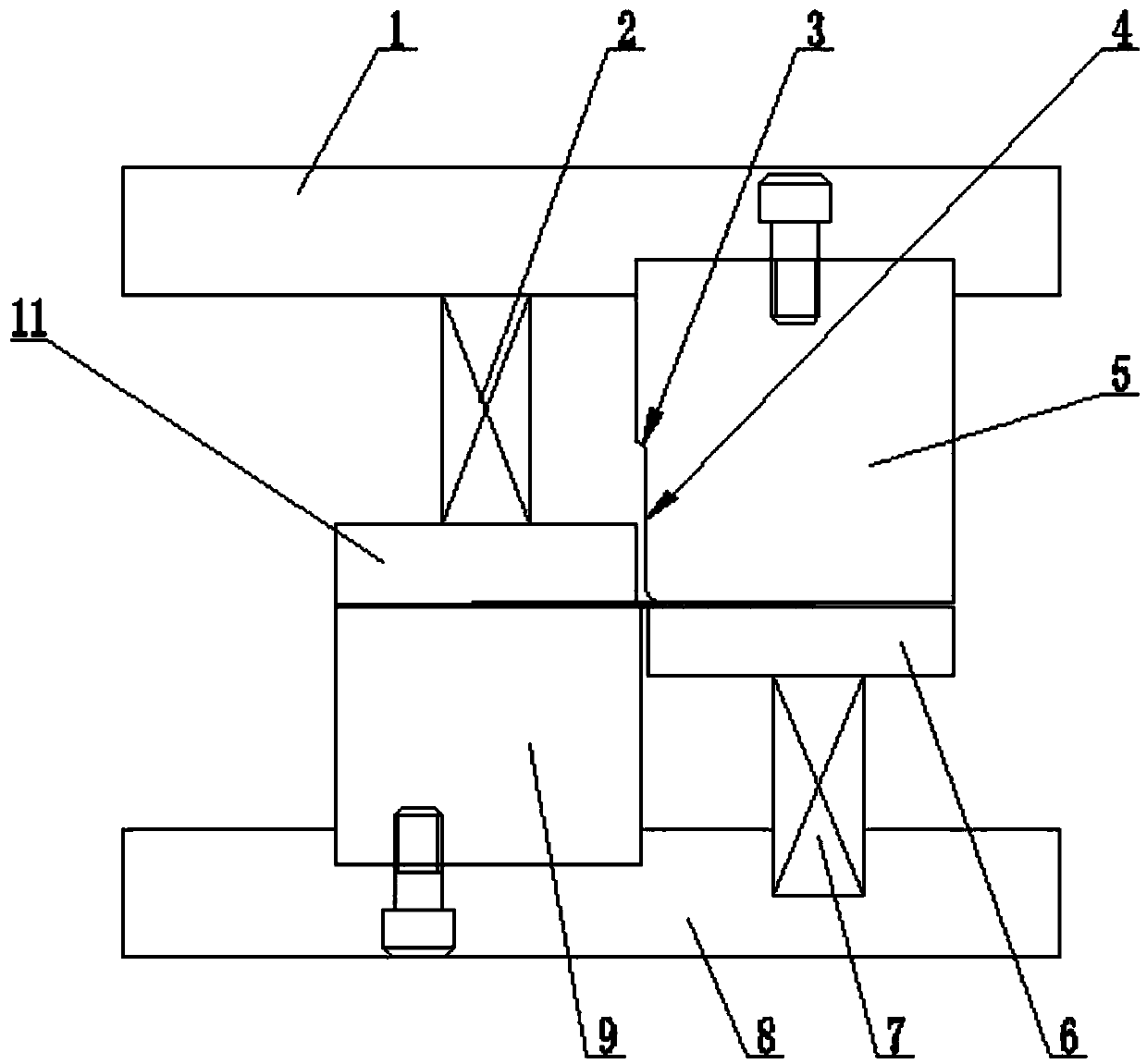
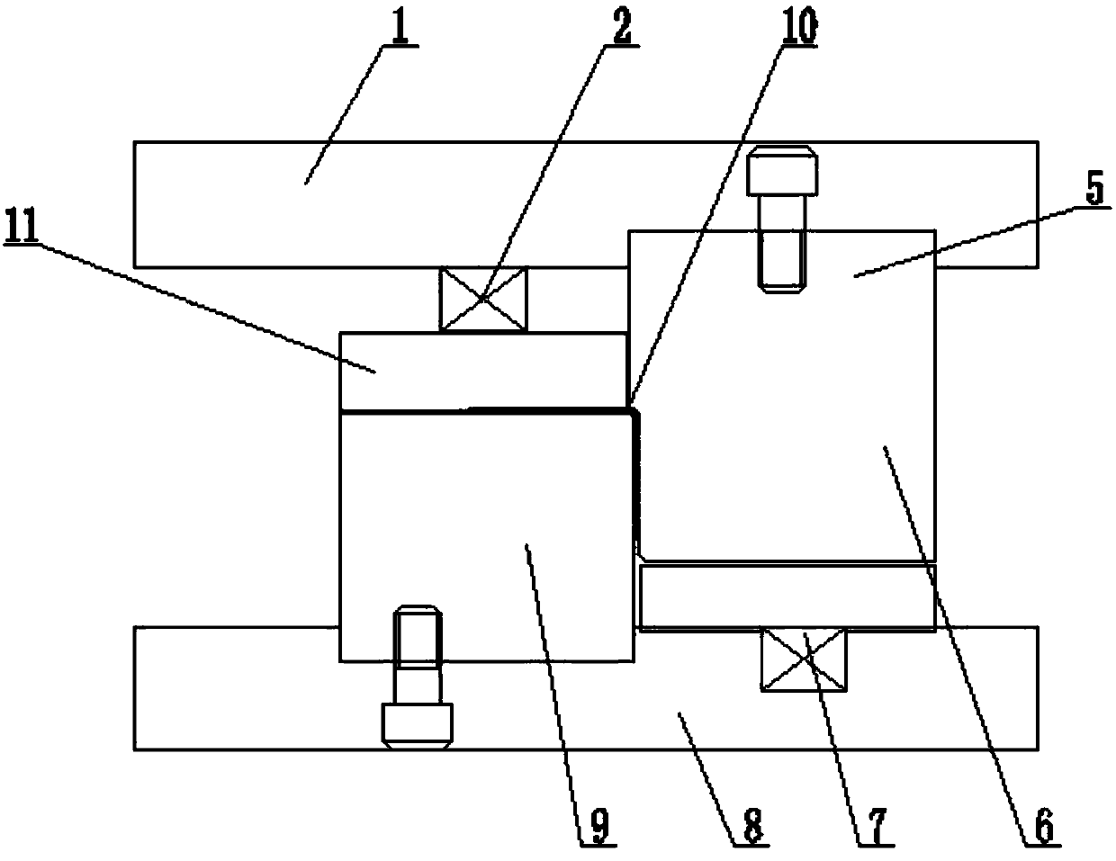
[0016] A mold device for drawing flanging, comprising an upper mold base 1 and a lower mold base 8, a punch 5 is installed in the upper mold base, and a die is installed in the lower mold base beside the punch 9. A molding groove 4 is made at the lower end of the same side of the male mold as the groove, and a rounded corner 3 is made at the upper end of the molding groove. An upper binder plate 11 is installed in the mold base, which can reciprocate in the vertical direction during the molding process, and a lower binder plate 6 is installed in the lower mold base at the corresponding position below the punch. , the lower pressing plate can reciprocate in the vertical direction during the forming process. Before the forming process, the ...


PUM


Abstract

The invention relates to the field of stamping dies, in particular to a die device for achieving drawing flanging forming. The device comprises an upper die base and a lower die base, wherein a male die is installed in the upper die base, a female die is installed in the lower die base beside the male die, a forming groove is formed in the lower end of the end part, on the same side with the female die, of the male die, a round angle is formed in the upper end part of the forming groove, an upper material pressing plate is arranged in the position, corresponding to the upper portion of the female die, of the upper die base, the upper material pressing plate can move in a reciprocating mode in the vertical direction in the forming process, a lower material pressing plate is arranged in theposition, corresponding to the lower portion of the male die, of the lower die base, the lower material pressing plate can move in a reciprocating mode in the vertical direction in the forming process, before the forming process, a gap is formed between the lower end surface of the upper material pressing plate and the upper end surface of the female die, the gap can allow a part to pass through,the position of the upper end surface of the lower material pressing plate is not higher than the horizontal position of the upper end surface of the female die, and an upper pressure spring is installed between the upper material pressing plate and the upper die base.

Description

technical field [0001] The invention relates to the field of stamping dies, in particular to a die device for realizing drawing flanging forming. Background technique [0002] With the development of technology and the increasingly fierce market competition, the traditional stamping process has also been changed to reduce the number of stamping processes and machine tools used, thereby achieving the purpose of saving costs. [0003] In the field of stamping dies, drawing is a stamping process that changes flat wool or process parts into a curved surface shape. The structure of the existing drawing device mainly includes an upper mold base and a lower mold base, and a punch is installed in the upper mold base. , a concave mold is installed in the lower mold seat on the side of the punch, a molding groove is made at the lower end of the same side of the punch and the concave mold, and a rounded corner is made at the upper end of the molding groove. During the process, the pun...

Claims


Application Information

Patent Timeline
Patent Type & Authority Applications(China)
IPC IPC(8): B21D37/10B21D43/00
Inventor 林世大
Owner 天津世亚模具股份有限公司
Learn More