An assembled I-beam

An I-beam and assembled technology, applied in the direction of feeding devices, manufacturing tools, metal processing, etc., can solve difficult and dangerous problems, and achieve the effects of improving service life, increasing contact surface, and uniform force

Inactive Publication Date: 2021-03-19
湖南润鑫建设有限公司
View PDF9 Cites 0 Cited by
  • Summary
  • Abstract
  • Description
  • Claims
  • Application Information

AI Technical Summary

Problems solved by technology

[0004] The purpose of the present invention is to provide an assembled I-beam to solve the technical problem of high difficulty and high risk of simply hammering the bending part in the prior art

Method used


Image

  • An assembled I-beam
  • An assembled I-beam
  • An assembled I-beam

Examples


Embodiment approach

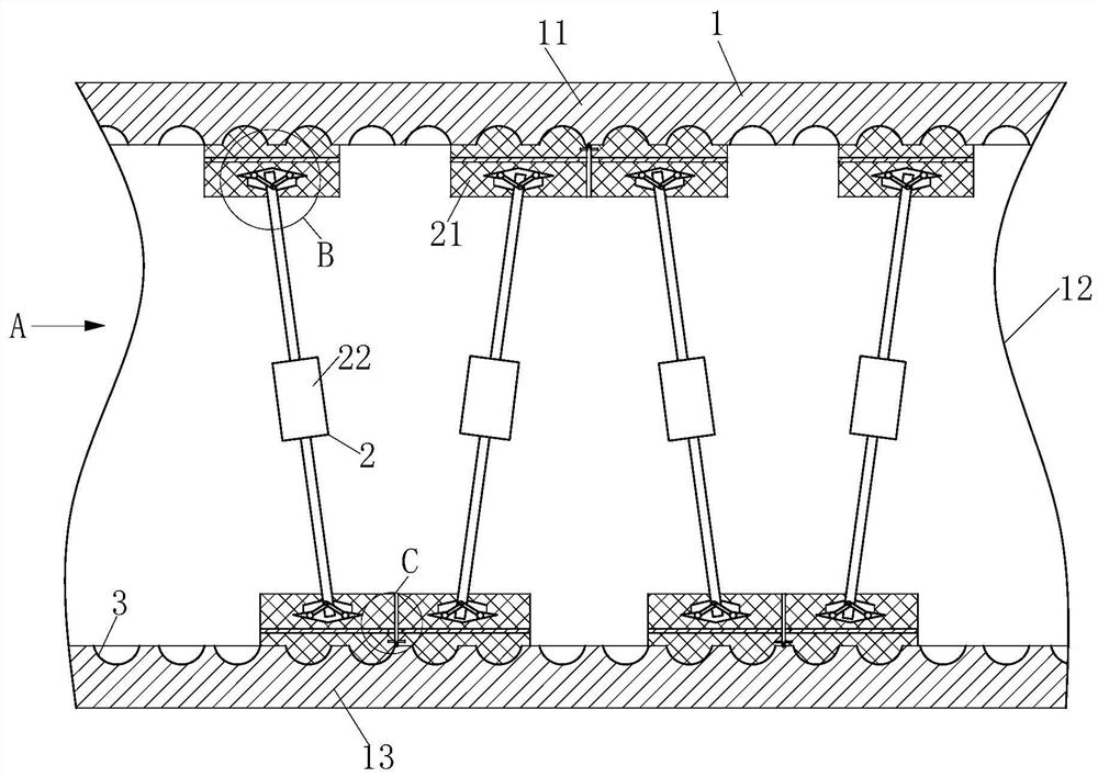
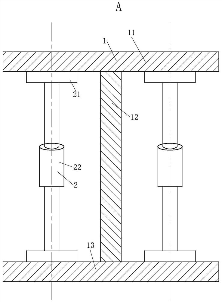
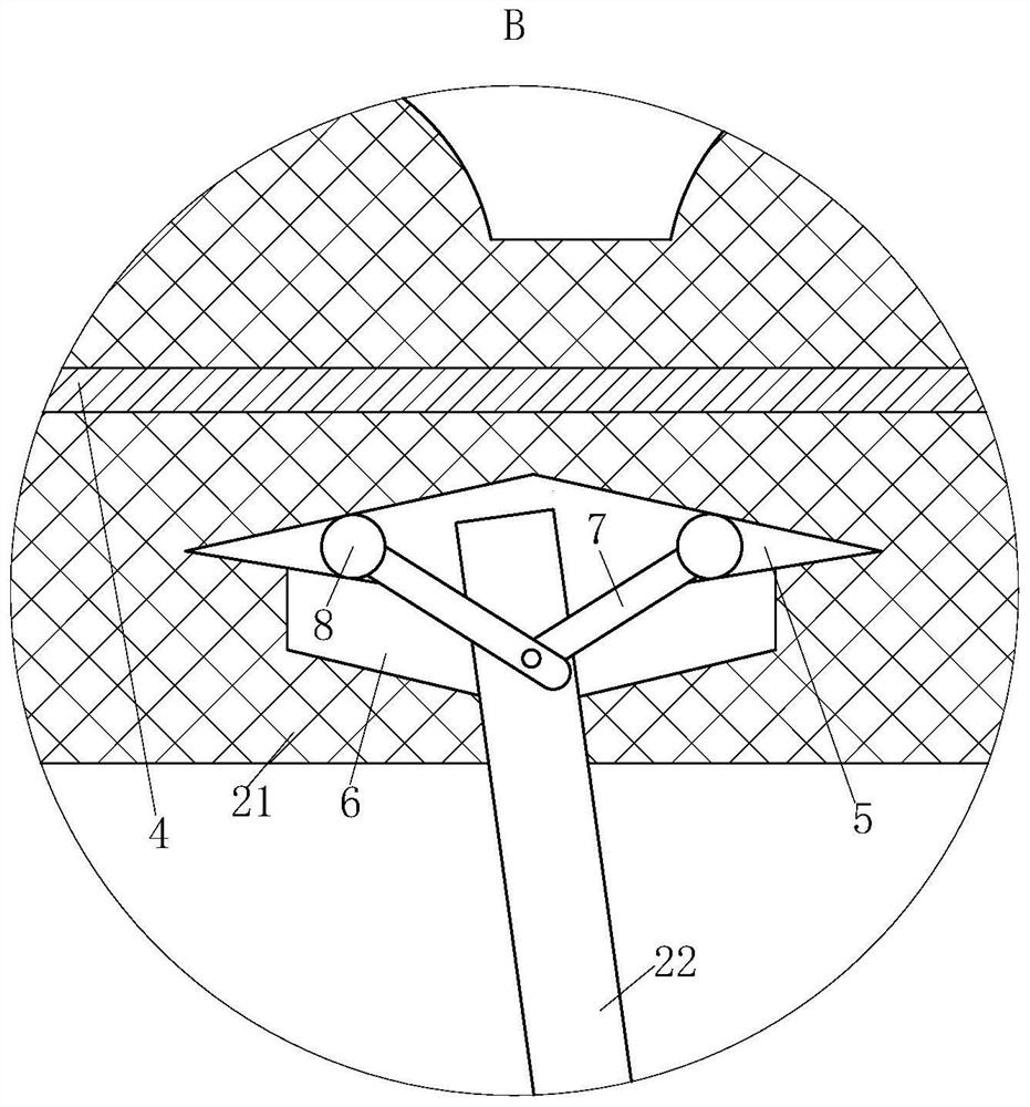
[0022] As an embodiment of the present invention, the support plate 21 is made of nylon, and a No. 1 groove is provided in the middle of the support plate 21, and the metal plate 4 is fixedly installed in the No. 1 groove. The metal plate 4 in the No. 1 groove can be replaced with the material of the plate according to the supporting strength of the I-beam 1, and the replacement is convenient. The correction module 2 can be used for the correction of the I-beam 1 of different materials; the support plate 21 made of nylon and the I-beam The contact effect of 1 is good, and the support plate 21 made of nylon has toughness and is not easy to break; but the support plate 21 made of nylon has low support strength, low hardness, and is easy to bend; so the piston rod of the biaxial hydraulic cylinder 22 and the support plate 21 are not Direct contact, the piston rod of the biaxial hydraulic cylinder 22 is in contact with the metal plate 4, the piston end of the biaxial hydraulic cyli...


PUM

PropertyMeasurementUnit
thicknessaaaaaaaaaa

Abstract

The invention belongs to the technical field of steel, and particularly relates to assembled joist steel. A joist steel body, correcting modules and a controller are included. The controller is used for controlling work of the correcting modules. The joist steel body comprises a first panel, a web and a second panel, wherein the web is vertically connected with the first panel and the second panel, and the first panel is located on the upper side of the second panel. A plurality of hemispherical grooves are evenly formed in the opposite side faces of the first panel and the second panel. The correcting modules are symmetrically distributed on the two sides of the web and obliquely placed, the adjacent correcting modules are opposite in inclination direction, a triangular structure is formed among the correcting modules, the first panel and the second panel, and each correcting module comprises a supporting plate and a double-shaft hydraulic cylinder. A shaft sleeve is arranged on one side of each supporting plate, a hemispherical protrusion is arranged on the other side of each supporting plate, and the protrusions are engaged with the hemispherical grooves. The end portions of piston rods of the double-shaft hydraulic cylinders are inserted in the shaft sleeves of the supporting plates, and the double-shaft hydraulic cylinders stretch and contract at the same time.

Description

technical field [0001] The invention belongs to the technical field of steel materials, and in particular relates to an assembled I-beam. Background technique [0002] I-beam, also known as steel beam, is a long strip of steel with an I-shaped cross section. I-beams are divided into ordinary I-beams and light I-beams. Ordinary I-beam and light I-beam flanges are thicker at the web and thinner on the outside. Ordinary I-beams and light I-beams have formed national standards. H-beams are also called wide-flange I-beams. Among them, HW and HN I-beams have been widely used and produced in my country. In domestic steel structure engineering, if the quantity is small, steel plates of the same specification can be used for welding and splicing. If the quantity is large, it is usually considered to use mechanical properties and The equivalent HW, HN steel instead. Traditional I-beams have low pressure resistance. During stacking or use, I-beams are prone to damage due to excessive ...

Claims


Application Information

Patent Timeline
Patent Type & Authority Patents(China)
IPC IPC(8): B21D3/00B21D43/00B21C51/00F16S3/00E04C3/06
Inventor 肖成美张顺陈杰
Owner 湖南润鑫建设有限公司
Why Eureka
Try Eureka