Transformer and power converter having same
A transformer and winding technology, applied in the direction of transformer/inductor core, transformer, transformer/inductor components, etc., can solve the problems of increasing the excitation current and increasing the transformer gap, and achieve the effect of suppressing abnormal heating
- Summary
- Abstract
- Description
- Claims
- Application Information
AI Technical Summary
Problems solved by technology
Method used
Image
Examples
no. 1 approach
[0043] 1.1 General structure
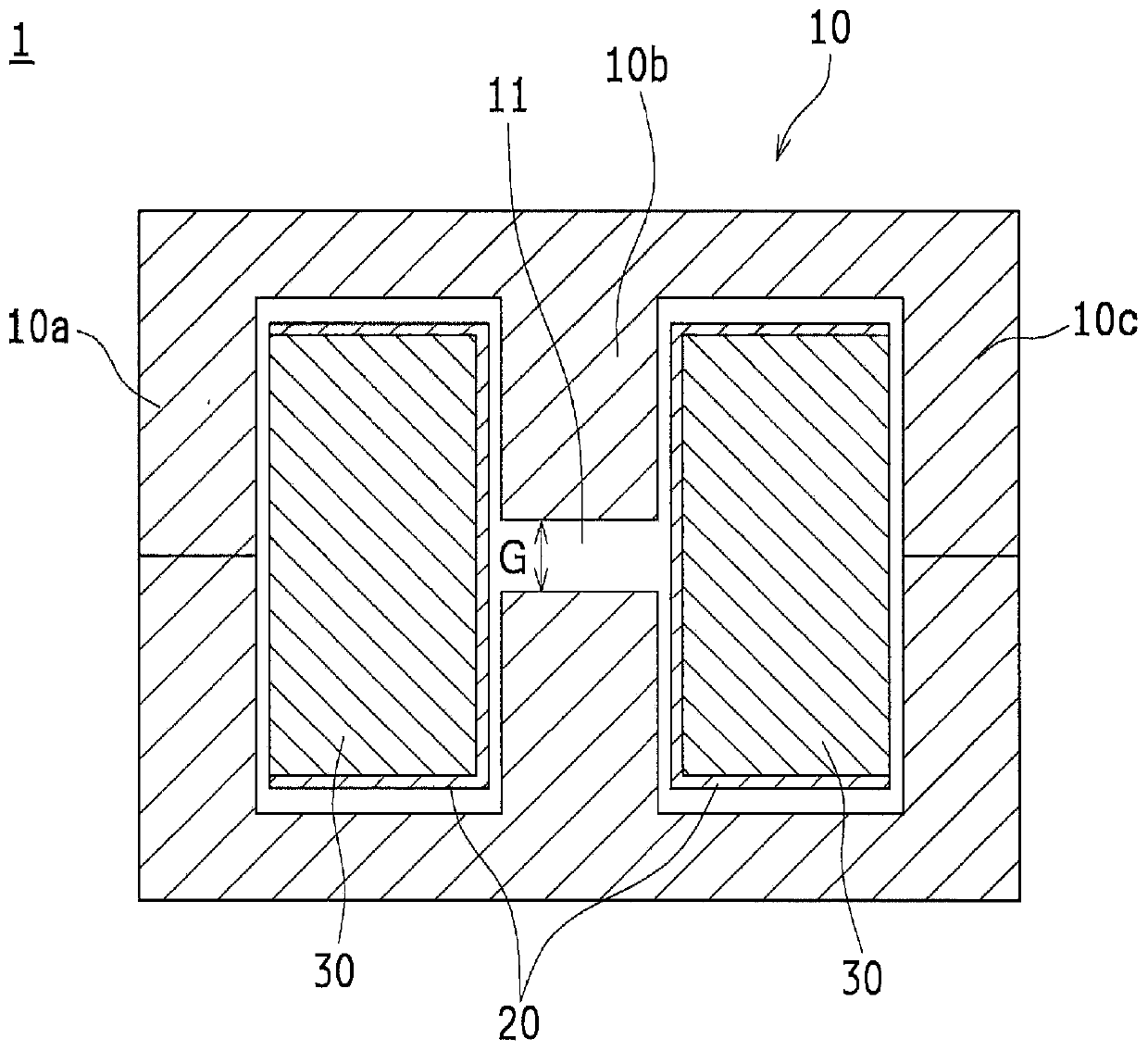
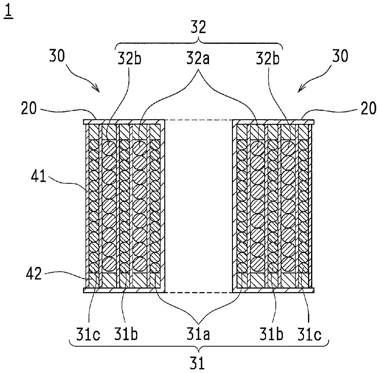
[0044] figure 1 It is a sectional view showing the general structure of the transformer 1 according to the first embodiment of the present invention. figure 2 It is a sectional view showing details of the winding portion 30 of the transformer 1 .
[0045] Such as figure 1 As shown, the transformer 1 has: an iron core 10, which forms a magnetic circuit, and is provided with a gap 11 at the middle leg 10b; a winding frame (winding frame) 20, which is installed on the middle leg 10b of the iron core 10; and The winding part 30 is wound on the bobbin 20 in multiple layers.
[0046] The iron core 10 has a middle foot 10b and two outer feet 10a, 10c branched from the middle foot 10b (respectively called the left foot 10a, the right foot 10c to distinguish if necessary), wherein the middle foot 10b A gap 11 is provided. The gap 11 is provided to prevent magnetic saturation of the iron core 10 or to adjust the excitation inductance of the transform...
no. 2 approach
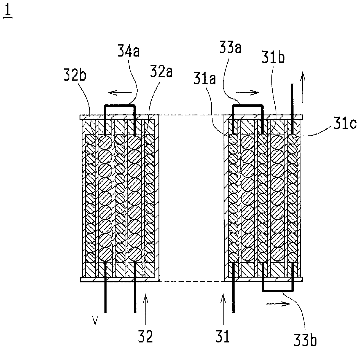
[0071] Figure 9 It is a sectional view illustrating the electrical connection between the layers of the first winding 31 and the second winding 32 of the transformer 1A according to the second embodiment of the present invention. In addition, the same reference numerals are assigned to the same components as those of the first embodiment, and the following description will mainly be made on the points of difference.
[0072] Such as Figure 9 As shown, in the transformer 1A, the layer 31a and the layer 31b of the first winding 31 are connected in series, and the layer 31b and the layer 31c are connected in parallel. That is, a specific layer (here, layer 31b) of the first winding 31 is connected in series to each layer (here, only layer 31a) on the inside (the side closer to the gap 11 ) than it, and the specific layer (here, layer 31b) Each layer (here, only the layer 31c ) on the outer side (the side farther from the gap 11 ) is connected in parallel.
[0073] Each layer...
no. 3 approach
[0076] Figure 10 It is a sectional view showing the general structure of the transformer 1B and the electrical connection between the layers of the first winding 31 and the second winding 32 according to the third embodiment of the present invention. In addition, the same reference numerals are attached to the same components as those of the first embodiment and the second embodiment, and the differences will be mainly described below.
[0077] When connecting the windings in series, a method may be considered in which separate windings are wound on each layer and the ends thereof are connected in series by welding or the like. However, in this case, man-hours for connection work are required.
[0078] Therefore, as a structure for holding the connecting wires for connecting the respective layers in series, the winding frame 20 is provided with connecting wire holding portions 21 . For example, it is also possible to dig out such a groove in the reel 20 that the connecting w...
PUM
 Abstract
Description
Claims
Application Information
 - R&D
- Intellectual Property
- Life Sciences
- Materials
- Tech Scout
- Unparalleled Data Quality
- Higher Quality Content
- 60% Fewer Hallucinations
Browse by: Latest US Patents, China's latest patents, Technical Efficacy Thesaurus, Application Domain, Technology Topic, Popular Technical Reports.
© 2025 PatSnap. All rights reserved.Legal|Privacy policy|Modern Slavery Act Transparency Statement|Sitemap|About US| Contact US: help@patsnap.com


