Packer test device and use method

A test device and packer technology, which is applied in the direction of measuring devices, machine/structural component testing, instruments, etc., can solve the problems of high cost, unfavorable general adoption, large space occupation, etc., and achieve the effect of convenient operation

Active Publication Date: 2021-03-30
CHINA NAT PETROLEUM CORP CHUANQING DRILLING ENG CO LTD +1
View PDF12 Cites 0 Cited by
  • Summary
  • Abstract
  • Description
  • Claims
  • Application Information

AI Technical Summary

Problems solved by technology

These two devices have complex structures, occupy a large space, are technically deficient, and have high costs, which are not conducive to widespread adoption.

Method used


Image

  • Packer test device and use method
  • Packer test device and use method

Examples


Embodiment 1

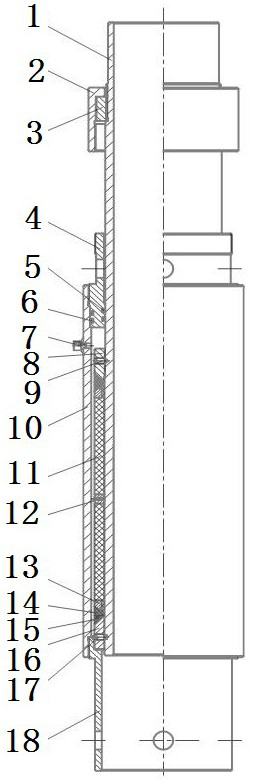
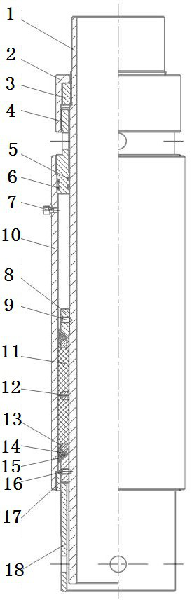
[0025] A packer test device, comprising a central pipe 1, a limit screw sleeve 2, a connecting screw sleeve 3, a sealing ring 4, a casing 10, an injection head 7, a push cylinder 18 and a packer, the packer includes a fixed screw Sleeve 8, rubber tube 11, spacer ring 12, pressure ring 13, male expansion ring 14, female expansion ring 15 and sliding sleeve 16, the fixed screw sleeve 8 is fixedly arranged in the middle of the central tube 1, at the center of the lower end of the fixed screw sleeve 8 The pipe 1 is provided with a female expansion ring 15, a male expansion ring 14, a compression ring 13, a rubber sleeve 11, a spacer ring 12, a rubber sleeve 11, a compression ring 13, a male expansion ring 14 and a female expansion ring 15 from top to bottom. The sliding sleeve 16 is fixed on the lower end of the central tube by the shear pin 17; the limit screw sleeve 2 is arranged on the upper part of the central tube 1, the sealing ring 4 is located between the limit screw sleeve...

Embodiment 2

[0035] This embodiment further illustrates the present invention in conjunction with the accompanying drawings.

[0036] Such as figure 1 As shown, a packer test device is composed of a central pipe 1, a limit screw sleeve 2, a connecting screw sleeve 3, a sealing ring 4, a casing 10, an injection head 7, a pusher 18 and a packer. The device consists of a fixed screw sleeve 8, a rubber cylinder 11, a spacer ring 12, a pressure ring 13, a male expansion ring 14, a female expansion ring 15 and a sliding sleeve 16 and the like. Described fixed screw sleeve 8 is installed in the middle part of center tube 1 by thread, and the lower end is male taper, and is fixed with pin 9, then on central tube 1 and the lower end of fixed screw sleeve 8, female expansion ring 15, male expansion ring are installed successively. Ring 14, pressure ring 13, rubber cylinder 11, spacer ring 12, rubber cylinder 11, pressure ring 13, male expansion ring 14, female expansion ring 15 and sliding sleeve 1...


PUM


Abstract

The invention discloses a packer test device and an application method thereof. The packer test device comprises a center tube, a limiting threaded sleeve, a connection threaded sleeve, a sealing ring, a shell, an injection head, a push barrel and a packer; the packer comprises a fixing threaded sleeve, a rubber barrel, a spacer ring, a pressure ring, a male expander ring, a female expander ring and a sliding sleeve; the fixing threaded sleeve is fixed to the center of the center tube; the sliding sleeve is fixed to the lower end of the center tube through a shear pin; the limiting threaded sleeve is arranged at the upper portion of the center tube; the sealing ring is positioned between the limiting threaded sleeve and the fixing threaded sleeve; the upper end of the shell is fixedly connected with the sealing ring; the lower end of the shell is connected with the push barrel; the injection head is positioned on the shell; the injection head is in clearance communication with the sealing ring and the fixing threaded sleeve; the connection threaded sleeve is positioned in the limiting threaded sleeve. The packer test device allows pressure test to be quickly carried out for normaltemperature and high temperature packers; setting activation force, setting travel and setting force can be tested for a packer; the local structures, such as the packer structure and inner diameter of the shell, can be changed separately to carry out testing.

Description

technical field [0001] The invention discloses a packer test device for well cementing and completion in oil and gas fields and a use method thereof, and belongs to the technical field of oil and gas field cementing and completion tool manufacturing. Background technique [0002] In the cementing and completion of oil and gas fields, packers are often used to achieve effective isolation between tubing and casing or between technical casing and production casing. In the laboratory production test and inspection of packers, and in the research of new packers, it is often necessary to carry out indoor performance tests on the performance of packers, and special test devices need to be designed. [0003] In the prior art, the Chinese patent "CN103162946A" discloses a simulation test device for an external packer. The performance of the outer packer is not understood, resulting in problems such as the cement entering the oil layer and contaminating the oil layer due to the failu...

Claims


Application Information

Patent Timeline
Patent Type & Authority Patents(China)
IPC IPC(8): G01M13/00
Inventor 唐欣刘运楼张毅超李斌张皓月王娟张敏
Owner CHINA NAT PETROLEUM CORP CHUANQING DRILLING ENG CO LTD
Why Eureka
Try Eureka