Automatic discharge device for bearing ring
An automatic discharge and bearing ring technology, applied in transportation, packaging, conveyors, etc., can solve the problems of cumbersome operation, high product failure rate, collision and wear of bearing rings, etc., to expand the contact area, ensure contact stability, The effect of reducing friction and collision
- Summary
- Abstract
- Description
- Claims
- Application Information
AI Technical Summary
Problems solved by technology
Method used
Image
Examples
Embodiment 1
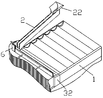
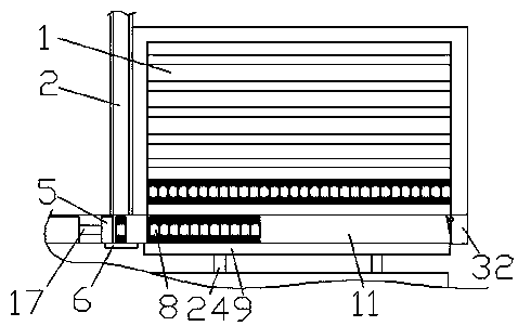
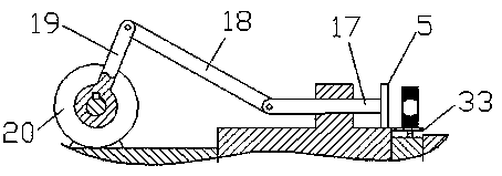
[0033] Such as Figure 1-10 As shown, an automatic discharging device for a bearing ring includes an obliquely arranged discharging groove 2, the width of the discharging groove 2 is slightly larger than the thickness of the bearing ring, and the top of the discharging groove 2 is provided with a semi-closed arc The hopper 22 is provided with a push rod mechanism on one side of the bottom of the discharging trough 2, a groove track 11 is provided on the other side of the bottom of the discharging trough 2, and the opposite side of the bottom of the discharging trough 2 is provided The baffle 6, the No. 1 push rod mechanism pushes a single bearing ring into the groove track 11, and the No. 2 push rod mechanism is arranged on one side of the baffle 6, and the No. 2 push rod mechanism arranges the groove track 11 A number of good bearing rings are pushed into the tray 1, and the inner section of the tray 1 is wavy;
[0034] The No. 1 push rod mechanism includes a No. 1 motor 20, a ...
Embodiment 2
[0041] This embodiment is a further optimization of embodiment 1, see Figure 4 , Figure 7 The contact surfaces of the No. 1 upper contact 30 and the No. 1 lower contact 31, the contact surfaces of the No. 2 left contact 34 and the No. 2 right contact 36 are all V-shaped with a concave-convex fit. This embodiment can expand the contact For the contact area of the head to ensure the contact stability, the other methods of this embodiment are the same as those of embodiment 1, and will not be repeated here.
Embodiment 3
[0043] This embodiment is a further optimization of embodiment 2, see Picture 9 A plurality of rubber rollers 4 are fixed on the push plate 9, and the distance between the rollers 4 is smaller than the thickness of the bearing ring, so as to convert the sliding friction between the push plate 9 and the bearing ring into rolling friction. The round roller 4 can absorb shock, reduce friction and collision; the inner bottom of the discharging trough 2 and the surface of the baffle 6 are equipped with rubber layers (not shown in the drawings in the manual) to ensure that the bearing ring rolls from the discharging trough 2 Roll down to the baffle 6, close and energize the No. 1 upper contact 30 and No. 1 lower contact 31 under the No. 1 reed 33, and use the No. 1 push rod mechanism to push the bearing ring onto the groove track 11. The design of the rubber layer has a protective effect on the bearing ring. The other modes of this embodiment are the same as those of Embodiment 1, an...
PUM
 Abstract
Description
Claims
Application Information
 - R&D
- Intellectual Property
- Life Sciences
- Materials
- Tech Scout
- Unparalleled Data Quality
- Higher Quality Content
- 60% Fewer Hallucinations
Browse by: Latest US Patents, China's latest patents, Technical Efficacy Thesaurus, Application Domain, Technology Topic, Popular Technical Reports.
© 2025 PatSnap. All rights reserved.Legal|Privacy policy|Modern Slavery Act Transparency Statement|Sitemap|About US| Contact US: help@patsnap.com


