
A sheet metal bending method and terminal

A sheet metal and bending machine technology, applied in metal processing, metal processing equipment, feeding devices, etc., can solve the problems of low production efficiency and high cost, and achieve the effect of improving efficiency, improving accuracy and reducing costs

Active Publication Date: 2020-03-31
福建渃博特自动化设备有限公司
View PDF7 Cites 0 Cited by
  • Summary
  • Abstract
  • Description
  • Claims
  • Application Information

AI Technical Summary

Problems solved by technology

[0003] However, the industrial robot bending fast programming system provided by the above-mentioned patent documents is applied in the sheet metal industry with the characteristics of small batch and multi-variety production, and the required cost is high and the production efficiency is low.

Method used


Image

  • A sheet metal bending method and terminal
  • A sheet metal bending method and terminal
  • A sheet metal bending method and terminal

Examples


Embodiment 1

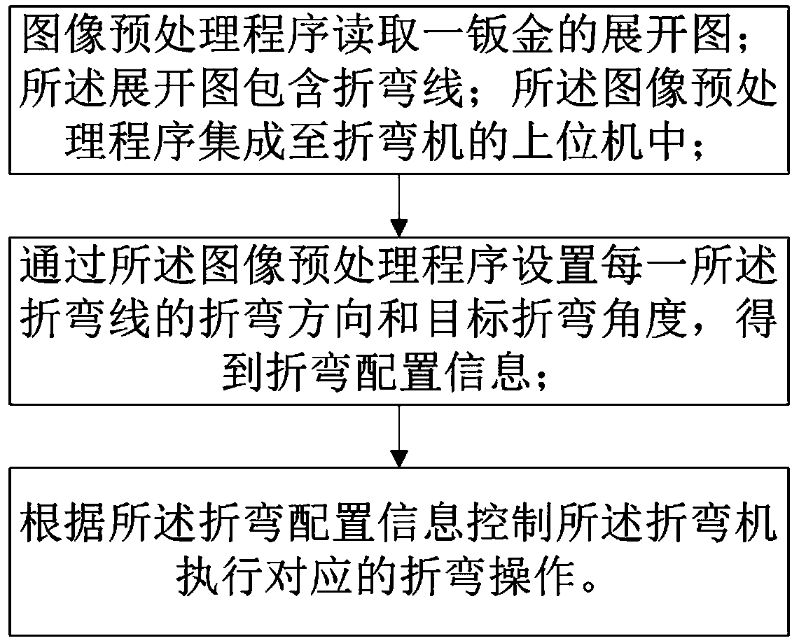
[0087] Such as figure 1 As shown, the present embodiment provides a sheet metal bending method, including:

[0088] S1. The image preprocessing program reads an unfolded view of a sheet metal; the unfolded view includes bending lines; the image preprocessing program is integrated into the host computer of the bending machine.

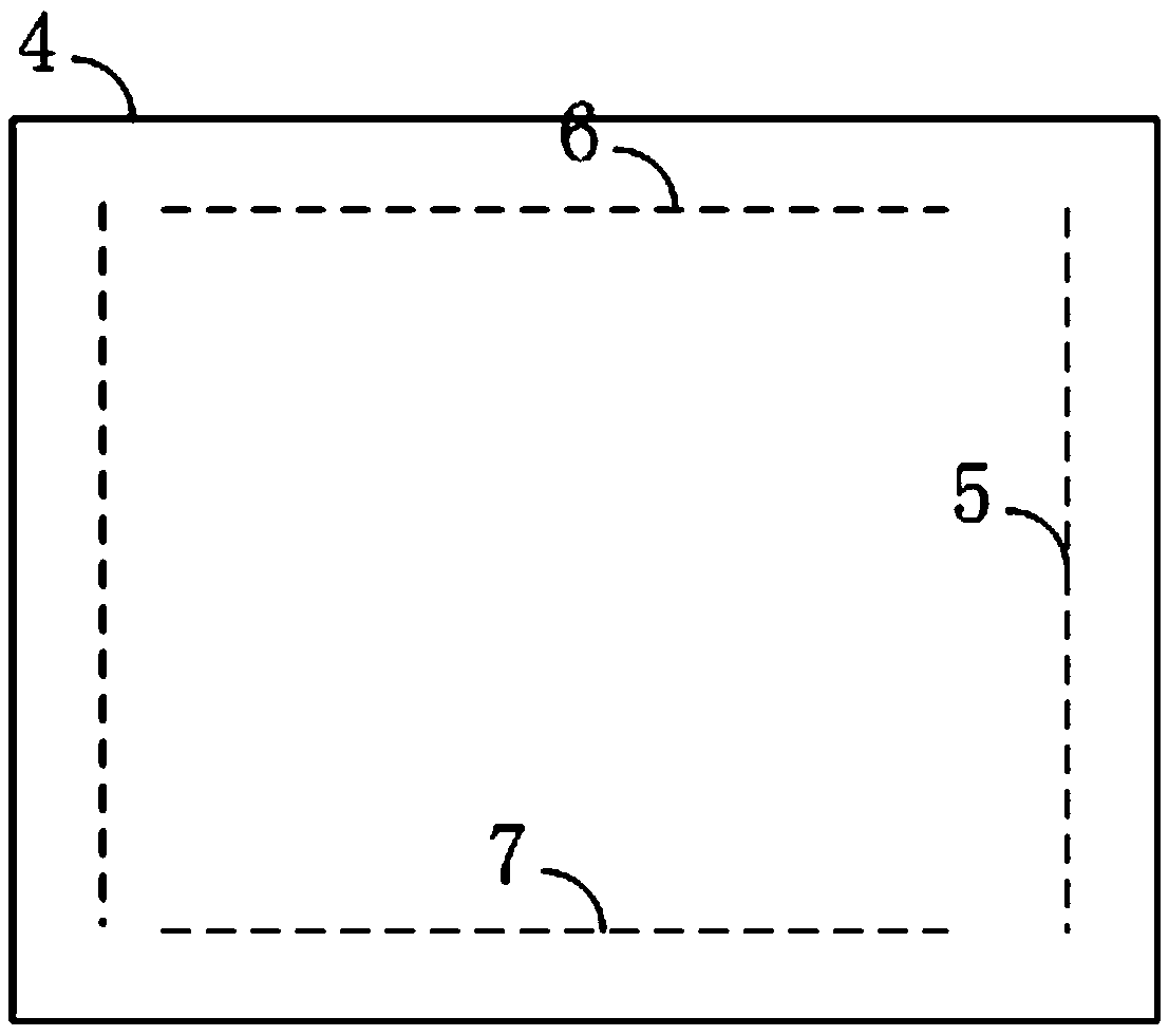
[0089] in, figure 2 It is an expanded view of a sheet metal, and the expanded view includes a first bending line 5 , a second bending line 6 and a third bending line 7 . The image preprocessing program can identify bend lines in the unfolded diagram and set configuration information for the bend lines.

[0090] S2. Set the bending direction and target bending angle of each of the bending lines through the image preprocessing program to obtain bending configuration information. Specifically:

[0091] S21. Select a bending line in the expanded view to obtain the current bending line;

[0092] S22. Select a bending direction from the preset drop-down...

Embodiment 2

[0184] Such as Figure 16 As shown, this embodiment provides a sheet metal bending terminal, including one or more processors 9 and a memory 10, the memory 10 stores a program and is configured to be executed by the one or more processors 9 The following steps:

[0185] S1. The image preprocessing program reads an unfolded view of a sheet metal; the unfolded view includes bending lines; the image preprocessing program is integrated into the host computer of the bending machine.

[0186] in, figure 2 It is an expanded view of a sheet metal, and the expanded view includes a first bending line 5 , a second bending line 6 and a third bending line 7 . The image preprocessing program can identify bend lines in the unfolded diagram and set configuration information for the bend lines.

[0187] S2. Set the bending direction and target bending angle of each of the bending lines through the image preprocessing program to obtain bending configuration information. Specifically:

[0...


PUM


Abstract

The invention relates to a metal plate bending method and terminal and belongs to the field of industrial automation. The metal plate bending method comprises the steps that an expanded view of a metal plate is read through an image preprocessing program, wherein the expanded view comprises bending lines, and the image preprocessing program is integrated into an upper computer of a bending machine; the bending direction and the target bending angle of each bending line are set through the image preprocessing program, so that bending configuration information is obtained; and the bending machine is controlled to implement corresponding bending operation through the bending configuration information. By means of the metal plate bending method, the bending production efficiency of the metal plate is improved, and the production cost is lowered.

Description

technical field [0001] The invention relates to a sheet metal bending method and a terminal, belonging to the field of industrial automation. Background technique [0002] The patent document with application number 201410541073.1 discloses a fast bending programming system for industrial robots, including a PLC monitoring module and a fast programming module. The PLC monitoring module includes a PLC memory information reading and input module, an information processing display module, and a bending process information module. Exchange module, PLC memory information reading and input module is connected with PLC controller; information processing display module is connected with PLC memory information reading and input module; bending process information exchange module is connected with information processing display module; fast programming The modules include drawing information reading module, drawing information preprocessing module, information analysis module, calcula...

Claims


Application Information

Patent Timeline
Patent Type & Authority Patents(China)
IPC IPC(8): B21D5/01B21C51/00B21D43/11B21D43/00
CPCB21C51/00B21D5/004B21D5/006B21D5/01B21D43/003B21D43/027B21D43/105B21D43/11B21D45/04
Inventor 翁伟郭进东
Owner 福建渃博特自动化设备有限公司
Learn More