Power semiconductor device

A technology of power semiconductors and devices, applied in the field of power semiconductor devices, can solve the problems of reverse leakage current of Schottky diodes, affect the life of Schottky diodes, affect the normal use of Schottky diodes, etc., and achieve high current surge impact , the effect of improving performance

Pending Publication Date: 2019-05-21
CHONGQING PINGWEI ENTERPRISE +1
View PDF5 Cites 0 Cited by
  • Summary
  • Abstract
  • Description
  • Claims
  • Application Information

AI Technical Summary

Problems solved by technology

During the use of the Schottky diode, an electric field will be generated near the Schottky barrier, which may cause the reverse leakage current of the Schottky diode, which not only affects the normal use of the Schottky diode, but also affects the Schottky diode. life

Method used


Image

  • Power semiconductor device
  • Power semiconductor device

Examples


Embodiment Construction

[0029] In the following description, numerous specific details are given in order to provide a more thorough understanding of the present invention. It will be apparent, however, to one skilled in the art that the present invention may be practiced without one or more of these details. In other examples, some technical features known in the art are not described in order to avoid confusion with the present invention.

[0030] It should be understood that the invention can be embodied in different forms and should not be construed as limited to the embodiments set forth herein. Rather, these embodiments are provided so that this disclosure will be thorough and complete, and will fully convey the scope of the invention to those skilled in the art. In the drawings, the size and relative sizes of layers and regions may be exaggerated for clarity. Like reference numerals refer to like elements throughout.

[0031] It will be understood that when an element or layer is referred t...


PUM


Abstract

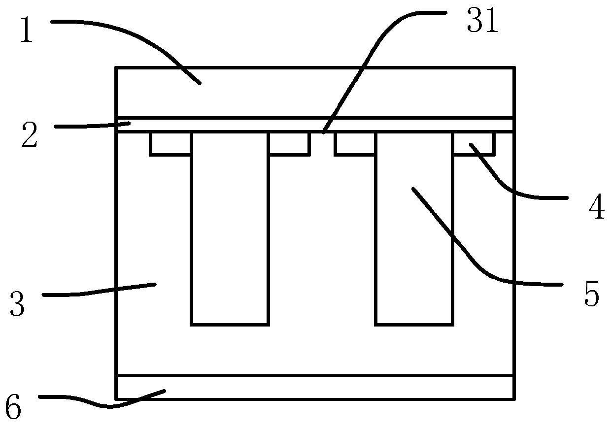
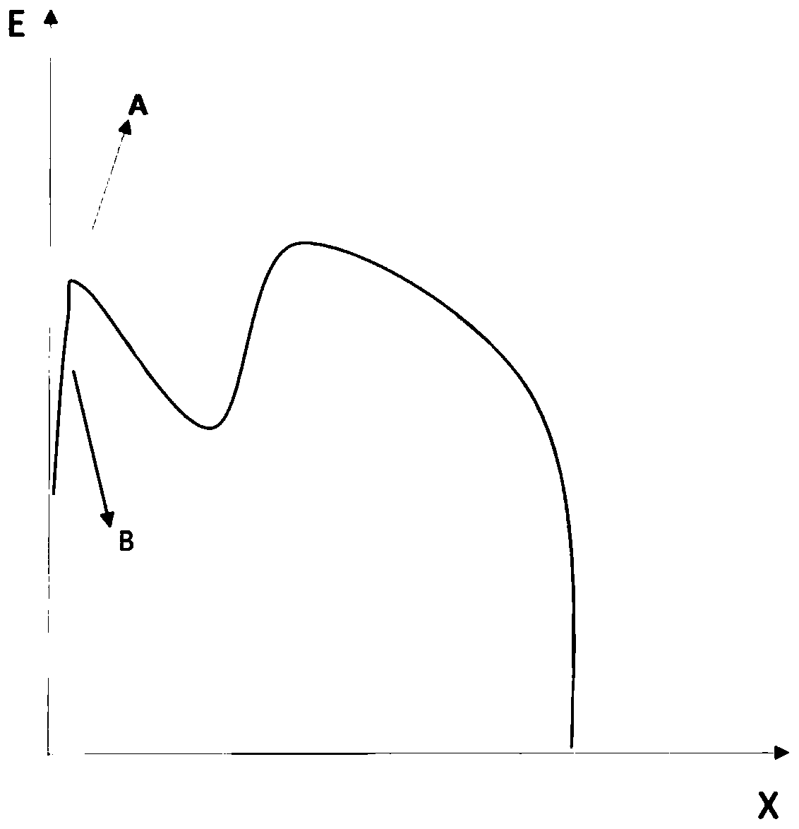
The invention provides a power semiconductor device. The power semiconductor device comprises a substrate, a first doping layer, a Schottky barrier layer and a metal layer, wherein the first doping layer, the Schottky barrier layer and the metal layer are stacked on the substrate in sequence; the first doping layer comprises a plurality of grids; and second doping layers are arranged on both sidesof each grid. The power semiconductor device with the second doping layers has relatively low peak electric field intensity, so that the peak electric field value of a table board is reduced and thenreverse leakage current of the power semiconductor device can be restrained; on the other hand, when the power semiconductor device bears large current impact, PN junctions formed by the second doping layers and the first doping layers are conducted; and compared with the Schottky barrier layer, the second doping layers can bear larger positive current density, so that larger current surge impactcan be borne, and the performance, using reliability and service life of the power semiconductor device can be improved and prolonged.

Description

technical field [0001] The invention relates to the technical field of semiconductors, in particular to a power semiconductor device. Background technique [0002] A Schottky diode is a metal-semiconductor device made with a metal electrode as the positive pole and an N-type semiconductor as the negative pole, and the potential barrier formed on the contact surface of the two has rectification characteristics. Because there are a large number of electrons in the N-type semiconductor and only a small amount of free electrons in the noble metal, the electrons diffuse from the N-type semiconductor with high concentration to the metal electrode with low concentration. As electrons continue to diffuse from the N-type semiconductor to the metal electrode, the electron concentration on the surface of the N-type semiconductor gradually decreases, and the surface electrical neutrality is destroyed, thus forming a potential barrier, and the direction of the electric field is from the ...

Claims


Application Information

Patent Timeline
Patent Type & Authority Applications(China)
IPC IPC(8): H01L29/872H01L29/06H01L21/329
Inventor 李述洲晋虎孙永生高良
Owner CHONGQING PINGWEI ENTERPRISE
Why Eureka
Try Eureka