
Box formwork construction method of assembly type box formwork hollow floor

A technology of hollow floor and construction method, applied in the direction of floor slab, structural elements, building components, etc., can solve the problems of consuming large technicians and the position conflict of stress bars in the structure of horse benches, so as to reduce the requirements of technicians, facilitate construction and operate simple effect

Inactive Publication Date: 2019-05-21
SHANGHAI ERSHIYE CONSTR CO LTD +1
View PDF5 Cites 0 Cited by
  • Summary
  • Abstract
  • Description
  • Claims
  • Application Information

AI Technical Summary

Problems solved by technology

For example, Zhao Hongsheng, Sun Zhong, and Li Honggang co-authored the article "Construction Method of Cast-in-situ Hollow Floor Structure (Hollow Formwork)" ("Building Structure. Technical Communication" in January 2007), in which the box formwork was fixed by using a well-shaped steel bar to support the horse stool. Although a better effect can be achieved by using a reinforced horse stool, the horse stool is likely to conflict with the position of the structural reinforcement during the construction process, and the manufacture and installation of the horse stool will consume a lot of technicians, so a simpler method is needed. Improve current construction methods

Method used


Image

  • Box formwork construction method of assembly type box formwork hollow floor
  • Box formwork construction method of assembly type box formwork hollow floor
  • Box formwork construction method of assembly type box formwork hollow floor

Examples


Embodiment Construction

[0020] Below in conjunction with specific embodiment, further illustrate the present invention. It should be understood that these examples are only used to illustrate the present invention and are not intended to limit the scope of the present invention. In addition, it should be understood that after reading the content taught by the present invention, those skilled in the art may make various changes or modifications to the present invention, and these equivalent forms also fall within the scope defined by the appended claims of the present application.

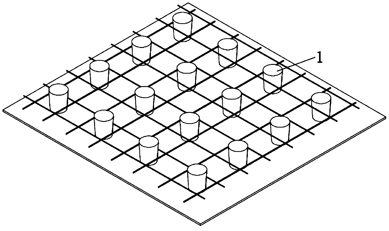
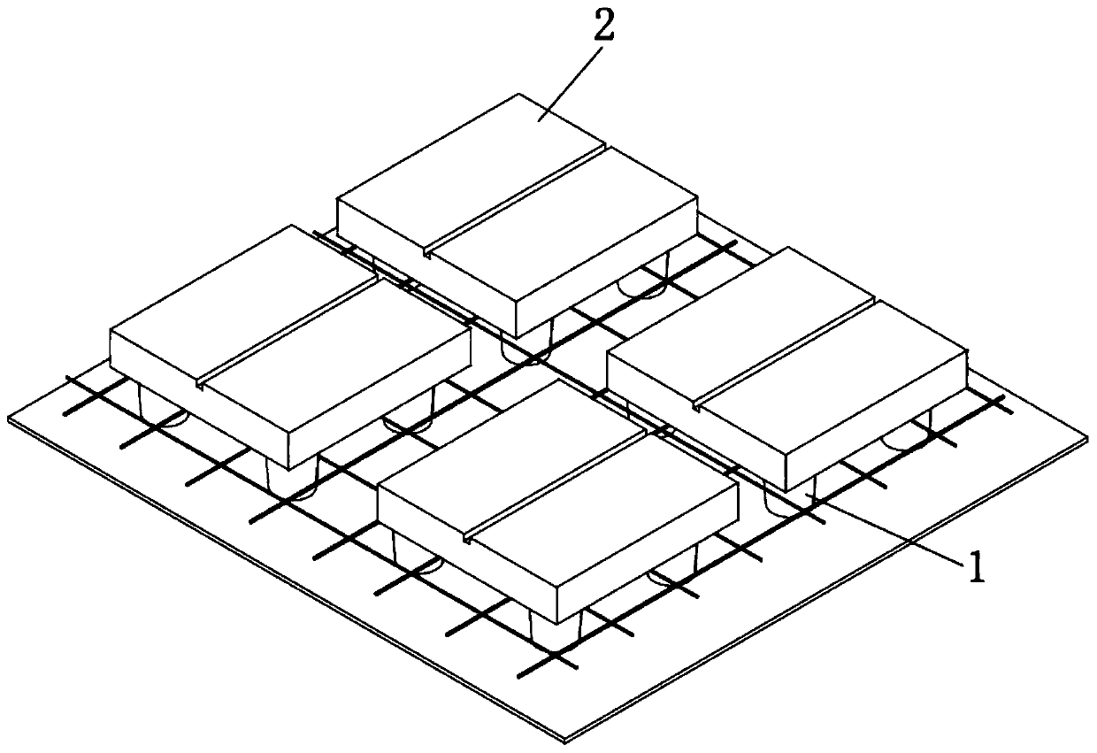
[0021] Such as Figure 1-4 A box formwork construction method for a prefabricated box formwork hollow floor shown, comprising the following steps:

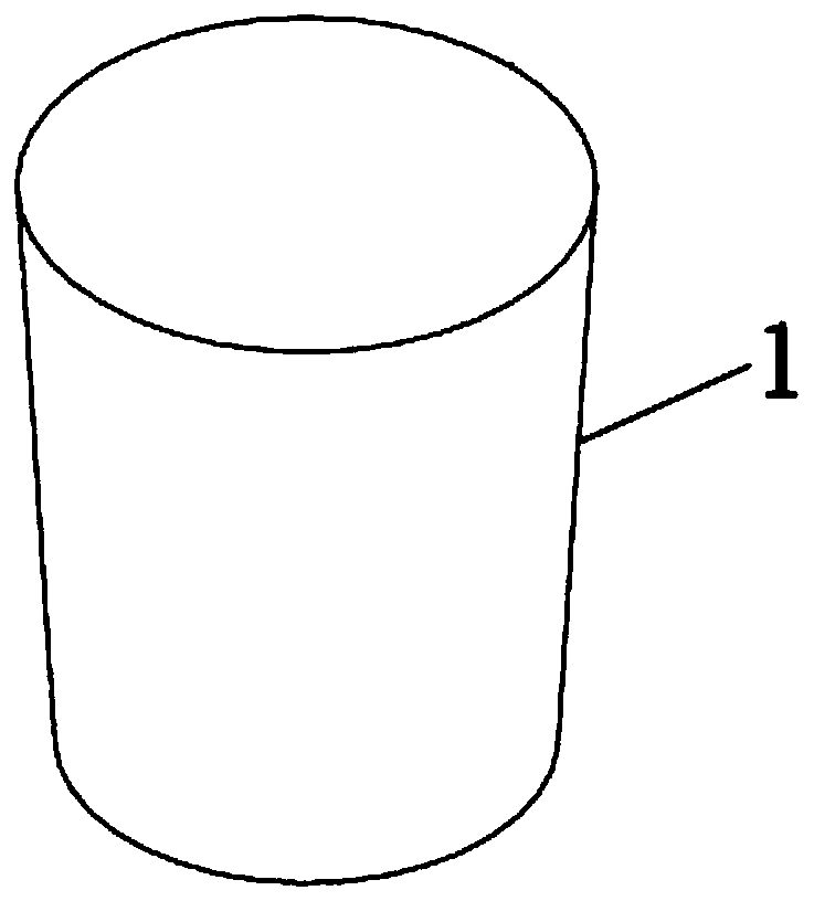
[0022] (1) Manufacture of wedge-shaped pad 1: Before the official construction, the concrete wedge-shaped pad 1 is made according to the design thickness of the cast-in-place layer of the lower flange of the floor, such as figure 1 Shown, wait for the wedge-shaped block 1 to...


PUM


Abstract

The invention relates to a box formwork construction method for an assembly type box formwork hollow floor. The box formwork construction method comprises the following steps of: manufacturing concrete wedge-shaped cushion blocks according to the design thickness of a floor lower flange cast-in-place layer; mounting floor slab bottom ribs, then arranging the wedge-shaped cushion blocks at positions shown in a box formwork design diagram, arranging four wedge-shaped cushion blocks at the bottom of each box formwork, and keeping the small-head ends of the wedge-shaped cushion blocks downwards and the large-head ends of the wedge-shaped cushion blocks upwards; arranging the box formworks at positions of the box formwork design diagram, placing the box formworks on the wedge-shaped cushion blocks, and supporting and positioning the box formworks through the four wedge-shaped cushion blocks; after the box formworks are installed, mounting floor slab surface ribs and inter-box-formwork rib beam steel bars, arranging anti-floating steel bars on the box formworks while the floor slab surface ribs are installed, arranging the anti-floating steel bars in the middles of the upper surfaces ofthe box formworks, and fixing the anti-floating steel bars to a floor slab bottom formwork through iron wires. On the premise that the construction quality is guaranteed, the construction difficulty is reduced, the construction efficiency is improved, and position conflicts between the box formwork positioning structure and the structural stress ribs are avoided.

Description

technical field [0001] The invention belongs to the technical field of floor box mold construction, in particular to a box mold construction method for an assembled box mold hollow floor. Background technique [0002] Assembled box-form hollow floor is a new type of building structure. Compared with traditional beam-slab structures, assembled box-form hollow floor is more suitable for structures with large bays, large spans, and large loads. It can not only effectively reduce the weight of the building , Improve the overall mechanical performance of the floor, and also enhance the thermal insulation, heat insulation, and sound insulation effects of the floor, especially suitable for basements, shopping malls, multi-storey factories, classrooms, meeting rooms, exhibition halls, gymnasiums, civil air defense projects, cinemas and other large rooms , large span, large load, strong sound insulation building structure. [0003] Assembled box formwork The key to the construction ...

Claims


Application Information

Patent Timeline
Patent Type & Authority Applications(China)
IPC IPC(8): E04B5/21E04B5/32E04C5/20
Inventor 吴仕飞徐明伍宇
Owner SHANGHAI ERSHIYE CONSTR CO LTD
Learn More