Eureka AIR delivers breakthrough ideas for toughest innovation challenges, trusted by R&D personnel around the world.

Clamping device for taper-cylindrical workpiece

A clamping device and workpiece technology, which are applied in the field of clamping devices for tapered and cylindrical workpieces, can solve the problems of position offset, inconvenient processing of tapered and cylindrical workpieces, large processing errors, etc., and achieve the effect of preventing positional shift.

Active Publication Date: 2019-05-21
WUHAN MARINE MACHINERY PLANT
View PDF7 Cites 13 Cited by
  • Summary
  • Abstract
  • Description
  • Claims
  • Application Information

AI Technical Summary

Problems solved by technology

[0003] Since the force direction of the cone-shaped workpiece is consistent with the axial direction of the cone body when processing the end face of the flange, when the conventional tension-type clamping device is used to clamp the cone-shaped workpiece, the cone-shaped workpiece will During the machining process, the cone-shaped workpiece is prone to shift along the axial direction of the cone body, resulting in large machining errors, which is not convenient for the processing of such cone-shaped workpieces.

Method used


Image

  • Clamping device for taper-cylindrical workpiece
  • Clamping device for taper-cylindrical workpiece
  • Clamping device for taper-cylindrical workpiece

Examples


Embodiment Construction

[0025] In order to make the object, technical solution and advantages of the present invention clearer, the implementation manner of the present invention will be further described in detail below in conjunction with the accompanying drawings.

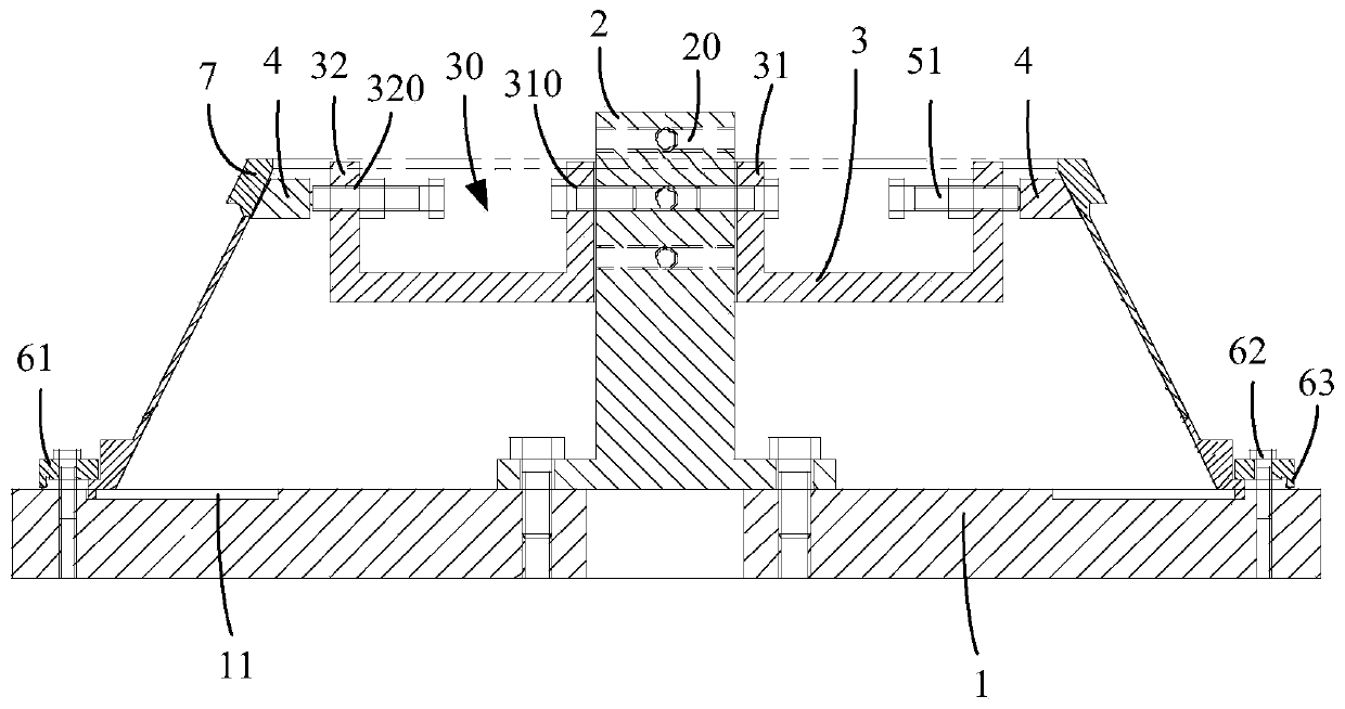
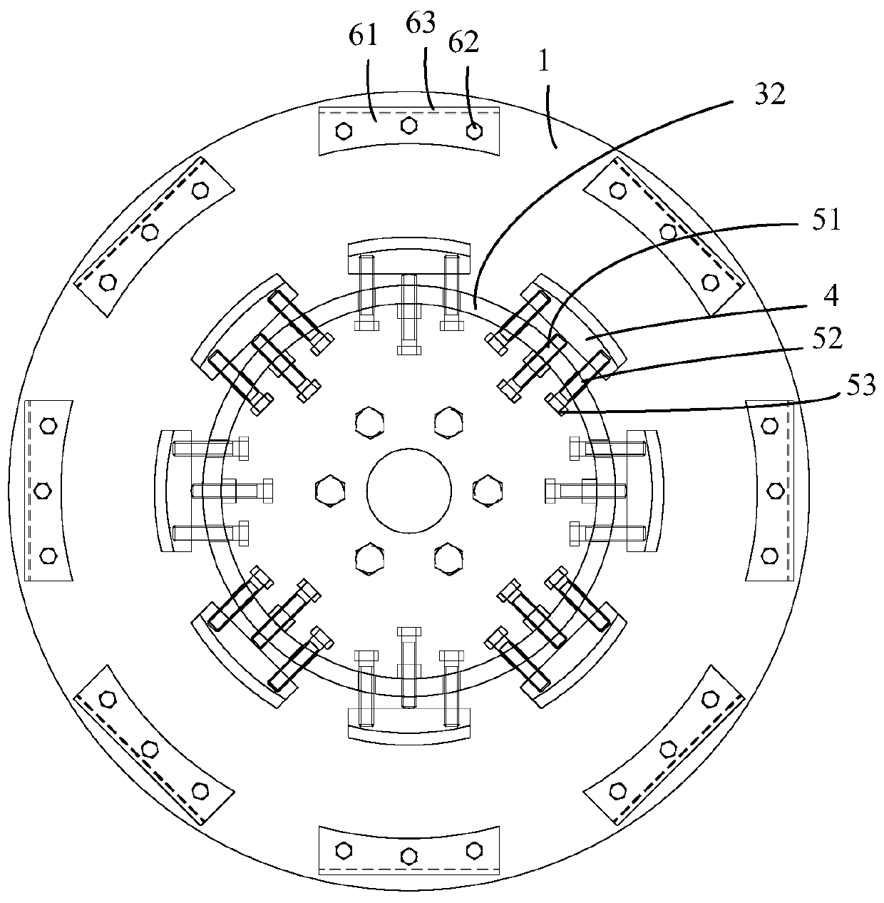
[0026] figure 1 It is a structural schematic diagram of a clamping device for a cone-shaped workpiece provided by an embodiment of the present invention. Such as figure 1 As shown, the clamping device includes: a positioning plate 1, a positioning pillar 2, a support ring 3, an expanding block 4, a positioning member and a pressing plate assembly. There is an annular positioning groove 11 on the side of the positioning disc 1 , and the annular side wall with a larger inner diameter is used to fit the outer wall of the flange at one end of the cone-shaped workpiece 7 . The positioning pillar 2 is located on one side of the positioning disk 1 , and the positioning pillar 2 is coaxially arranged with the positioning disk 1 . The suppor...


PUM


Abstract

The invention discloses a clamping device for a taper-cylindrical workpiece. The clamping device includes a positioning disc, a positioning strut, a supporting ring, an expanding block, a position adjusting piece and a pressure plate assembly, an annular positioning groove is formed in the side face of the positioning disc, the annular side wall with the large diameter inside the annular positioning groove is used for fitting the outer wall of a flange at one end of the taper-cylindrical workpiece, the positioning strut is located on one side face of the positioning disc and coaxially arrangedon the positioning disc, and the supporting ring is coaxial mounted on the positioning strut in a sleeving mode; and the supporting ring is detachably connected with the positioning strut, the expanding block is located on the outer edge side of the supporting ring, the expanding block is movably connected with the supporting ring, the end face, deviating from the positioning strut, of the expanding block is fitted with the inner wall of the taper-cylindrical workpiece, the positioning adjusting piece is configured to control the expanding block to slide in the radial direction of the supporting ring, and the pressure plate assembly is used for pressing and mounting one end of the taper-cylindrical workpiece on one side face of the positioning disc. The clamping device can prevent the position offset of the taper-cylindrical workpiece in the machining process, and the processing precision is improved.

Description

technical field [0001] The invention relates to the technical field of mechanical processing, in particular to a clamping device for a cone-shaped workpiece. Background technique [0002] In gas turbines, there are usually a large number of thin-walled workpieces, which have small wall thickness, high precision requirements, and a cone-shaped shape. This type of cone-shaped workpiece includes a cone body and flanges located at both ends of the cone body. It is usually necessary to process the two opposite end faces of the two flanges during the machining of such cone-shaped workpieces. [0003] Since the force direction of the cone-shaped workpiece is consistent with the axial direction of the cone body when processing the end face of the flange, when the conventional tension-type clamping device is used to clamp the cone-shaped workpiece, the cone-shaped workpiece will During the machining process, the cone-shaped workpiece is prone to positional deviation along the axial...

Claims


Application Information

Patent Timeline
IPC IPC(8): B23Q3/06
Inventor 张明杨松王臻杨家军熊永钊
Owner WUHAN MARINE MACHINERY PLANT
Why Eureka
Eureka Blog
Learn More