


Quick Research
Generate reliable direction feasibility study reports for your R&D in just a few steps.

Technical Q&A
Discover and master advanced knowledge NOW. Basics, ideas, possibilities, all at once.

Find Solutions
As an expert in R&D theories, this can generate solutions to your technical problems instantly.

Evaluate Feasibility
Analyze your overall solution with one click, know your potential R&D risks in advance.

Monitor Landscape
Get weekly tech updates, stay abreast of the latest tech innovations and key insights.
Sheet metal part forming method with multi-layer combined male die adopted
A technology of sheet metal parts and punches, which is applied in the field of forming metal sheet metal parts using multi-layer combined punches, can solve problems such as quality defects, unreasonable contact and action between punches and original slabs, and achieve uniformity improvement , Save mold repair time and prolong service life
- Summary
- Abstract
- Description
- Claims
- Application Information
AI Technical Summary
Problems solved by technology
Method used
Image

Examples
specific Embodiment approach 1
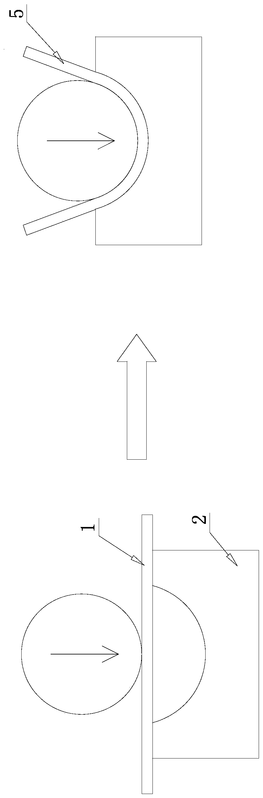
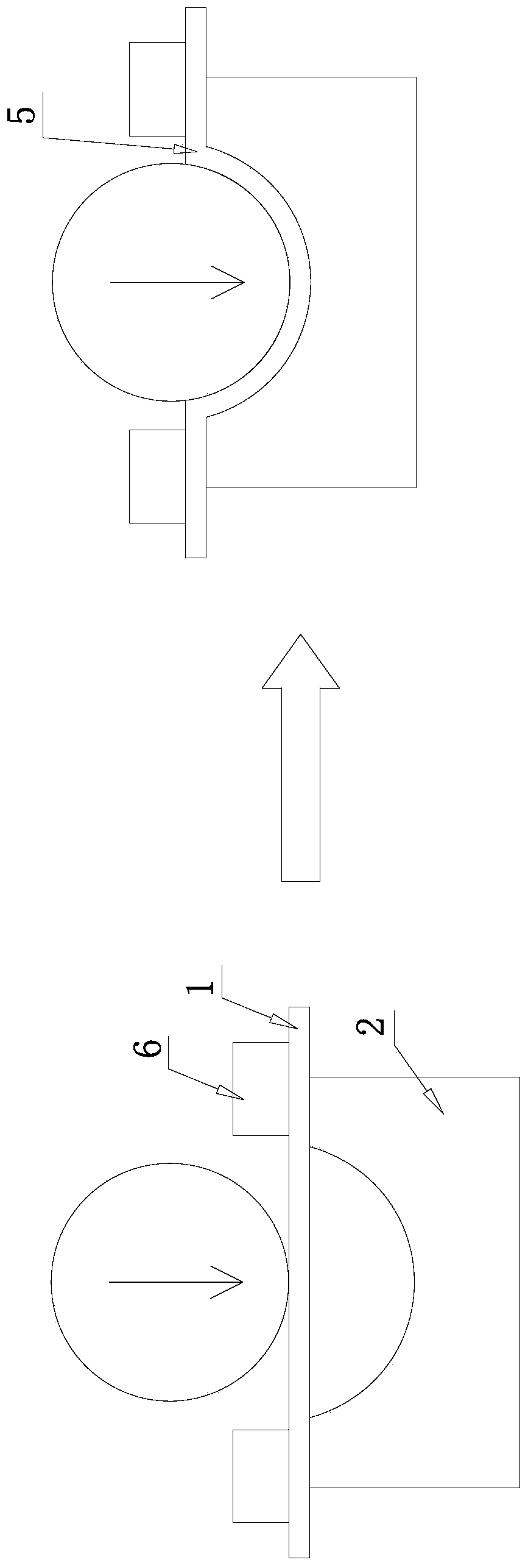
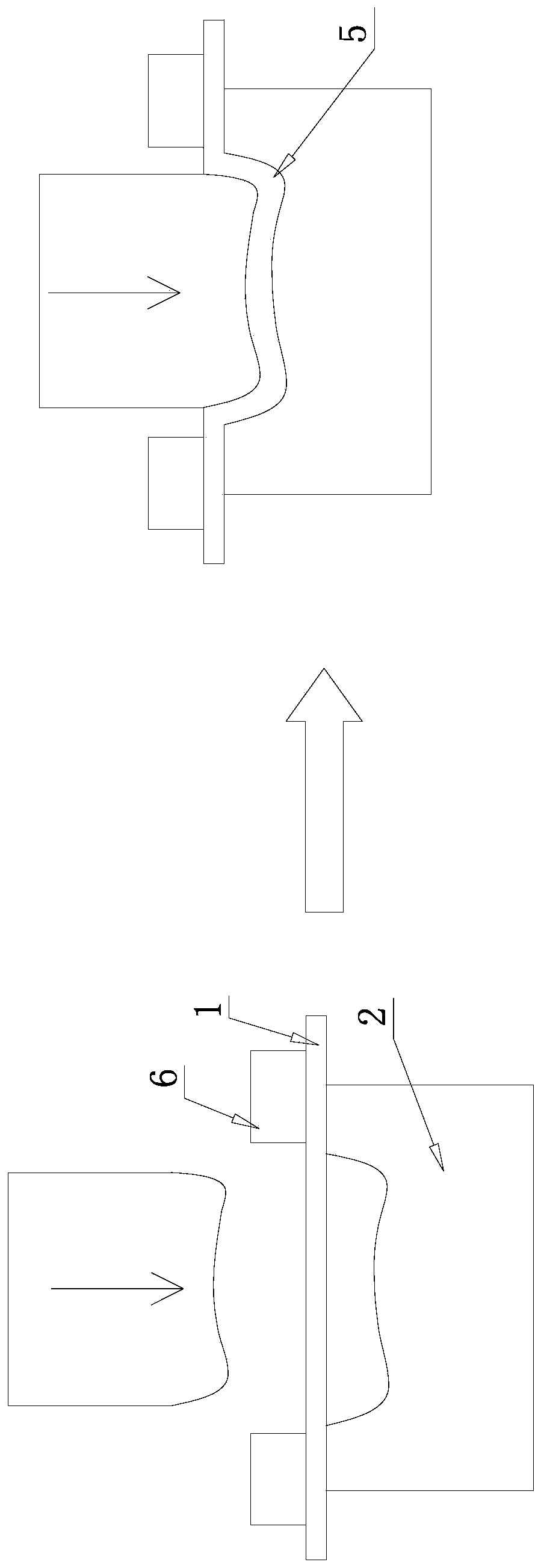
[0028] Specific implementation mode one: combine Figure 4-Figure 9 Illustrate, a kind of metal sheet metal part forming method that adopts multi-layer combined punch of this embodiment is realized according to the following steps:
[0029] Step 1, placing the blank 1 to be formed on the forming die 2 and positioning it;
[0030] Step 2, combining a plurality of plate-shaped molds 3-1 into a multi-layer combined punch 3 and positioning it at a suitable position above the blank 1;
[0031] Step 3, using the drive wheel 4 to drive the multi-layer combination punch 3, so that the multi-layer combination punch 3 gradually acts on the blank 1;
[0032] Step 4: After the blank 1 is completely fitted into the cavity of the forming die 2, the final sheet metal part 5 is obtained;
[0033] Step 5, remove the driving wheel 4 and the multi-layer combination punch 3, and remove the formed sheet metal part 5 from the forming die 2.
specific Embodiment approach 2
[0034] Specific implementation mode two: combination Figure 4 and Figure 5 Explain that the difference between this embodiment and the specific embodiment one is: the cavity of the forming die 2 in the step one is a circular or oval shape with a regular shape; the multilayer combined punch 3 in the step two is made of multilayer The plate mold 3-1 of about 20-50mm is formed, and the height and thickness of each plate mold 3-1 are identical and its bottom is all in contact with the upper surface of original blank 1 in initial state; In the step 3, the driving of driving wheel 4 is more The surface contour shape of the layer combination punch 3 is the same regular shape as the cavity of the die 2, and the driving wheel 4 rotates along the upper rotating shaft. Other steps and parameters are the same as in the first embodiment.
[0035] The beneficial effect of this embodiment is: since the multi-layer combination punch 3 is composed of plate-shaped molds of the same height a...
specific Embodiment approach 3
[0036] Specific implementation mode three: combination Figure 7 Explain that the difference between this embodiment and the specific embodiment one or two is: the forming die 2 in step one is an irregular shape, and the depth of the concave mold cavity changes irregularly; the multi-layer combined punch 3 in step two is It consists of multi-layer plate-shaped molds 3-1 with a thickness of 20-50mm. The height and thickness of each plate-shaped mold 3-1 are different, and the bottom of each plate-shaped mold 3-1 is in the initial state. Contact; in step 3, the surface profile of the drive wheel 4 driving the multi-layer combination punch 3 is circular, and the drive wheel 4 rotates along the upper rotation axis. Other steps and parameters are the same as those in Embodiment 1 or Embodiment 2.
[0037] The beneficial effect of this embodiment is: since the height and thickness of each plate-shaped mold adopted in step 2 are different, it is possible to obtain a punch shape that...
PUM
| Property | Measurement | Unit |
|---|---|---|
| yield strength | aaaaa | aaaaa |
| thickness | aaaaa | aaaaa |
Abstract
Description
Claims
Application Information
 - R&D Engineer
- R&D Manager
- IP Professional
- Industry Leading Data Capabilities
- Powerful AI technology
- Patent DNA Extraction
Browse by: Latest US Patents, China's latest patents, Technical Efficacy Thesaurus, Application Domain, Technology Topic, Popular Technical Reports.
© 2024 PatSnap. All rights reserved.Legal|Privacy policy|Modern Slavery Act Transparency Statement|Sitemap|About US| Contact US: help@patsnap.com