
A device and method for positioning a robotic arm based on laser scanning

A laser scanning and positioning device technology, which is applied in the direction of using optical devices, measuring devices, instruments, etc., can solve problems such as dimensional errors, geometric errors, interference, etc., to improve efficiency and accuracy, improve positioning accuracy, and reduce poses effect of error

Active Publication Date: 2021-04-27
CHINA RAILWAY CONSTR HEAVY IND
View PDF6 Cites 0 Cited by
  • Summary
  • Abstract
  • Description
  • Claims
  • Application Information

AI Technical Summary

Problems solved by technology

[0003] The multi-function trolley has long arm frame, many joints, heavy weight, and is prone to flexible deformation, and there are dimensional errors in the various parts after processing and assembly. It is very difficult to realize the precise positioning of the terminal operation device, which affects The factors of the positioning accuracy of the robot arm include deformation and geometric error
Usually, we use the robot kinematics modeling method to establish the jib kinematics calibration model based on the jib structure and motion rules. However, this method improves the positioning accuracy by identifying geometric errors, ignoring the large-scale and The deformation factor caused by low rigidity, and the flexible deformation of the boom will interfere with the identification of geometric errors
The jib of the trolley involves many unfavorable factors such as variable cross-section, contact, and clearance. The method of direct calibration through the whole is not suitable for the positioning of the jib of the multifunctional operation trolley. Therefore, a method that can directly identify and obtain the end pose of the mechanical arm is needed Methods

Method used


Image

  • A device and method for positioning a robotic arm based on laser scanning
  • A device and method for positioning a robotic arm based on laser scanning
  • A device and method for positioning a robotic arm based on laser scanning

Examples


Embodiment Construction

[0028] The implementation of the present invention will be described in detail below in conjunction with the accompanying drawings and examples, so as to fully understand and implement the implementation process of how to apply technical means to solve technical problems and achieve corresponding technical effects in the present invention. The embodiments of the present application and the various features in the embodiments can be combined with each other under the premise of no conflict, and the formed technical solutions are all within the protection scope of the present invention.

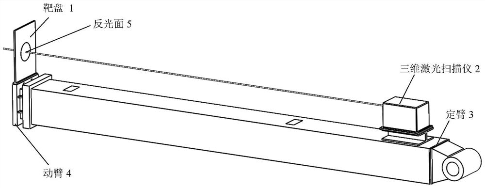
[0029] In this embodiment, taking a multi-functional operation trolley as an example, based on the structure of the boom of this trolley, it can be determined that the deformation of the telescopic arm is the most important reason for the low positioning accuracy of the boom of the trolley. The method of direct measurement on site is determined. Briefly speaking, the principle of the present in...


PUM


Abstract

The invention discloses a laser scanning-based mechanical arm positioning device and method, wherein the device includes: a target with an identifiable surface, which is installed at the setting end of the moving arm of the mechanical arm; a laser scanner, It is installed at the setting end of the fixed arm of the mechanical arm, and scans the target to obtain scanning parameters used to characterize the pose information of the end of the mechanical arm in the scanner coordinate system; the controller, according to The pose information of the scanner under the coordinate system of the manipulator carrier, the pose information of the manipulator carrier under the tunnel coordinate system, and the scanning parameters are calculated to obtain the position of the end of the manipulator under the tunnel coordinate system Attitude information, so as to complete the positioning of the robot arm. Compared with the prior art, the present invention improves the positioning accuracy of the boom, reduces the pose error caused by the deformation of the boom, and improves the efficiency and accuracy of target recognition.

Description

technical field [0001] The invention relates to the field of engineering machinery, in particular to a laser scanning-based positioning device and method for the end of a mechanical arm of a multifunctional work trolley. Background technique [0002] During the construction of tunnel engineering, in order to prevent the surrounding rock from deforming and breaking, it is usually necessary to reinforce the surrounding rock by erecting arches, installing anchor rods, hanging steel mesh, and spraying concrete. Take the tunnel arch multi-functional operation trolley as an example. This trolley is an automatic tunnel construction equipment integrating arch positioning, installation and welding. The core operating arm is a 10-degree-of-freedom series mechanism. It is the basic requirement of the multifunctional work trolley to realize the predetermined position and attitude of the terminal operation device by the joint pose, and it is also the key technology in its development. ...

Claims


Application Information

Patent Timeline
Patent Type & Authority Patents(China)
IPC IPC(8): G01B11/00
Inventor 刘飞香郑大桥秦念稳曾苗筠田朝猛邓泽张子明田旭朱灿一
Owner CHINA RAILWAY CONSTR HEAVY IND
Learn More