
Oil injector and engine

A fuel injector and fuel injector technology, which is applied to machines/engines, engine components, mechanical equipment, etc., can solve problems affecting the opening and closing of the fuel injector valve core, leakage, and changes in fuel injector volume, so as to prevent accidents from happening. Source, high efficiency, and the effect of preventing clogging

Pending Publication Date: 2019-05-17
ZHEJIANG GEELY HOLDING (GROUP) CO LTD +1
View PDF12 Cites 0 Cited by
  • Summary
  • Abstract
  • Description
  • Claims
  • Application Information

AI Technical Summary

Problems solved by technology

[0002] After a large number of tests, it was found that the combustion temperature of the methanol fuel engine is higher, and the moisture produced by the combustion is more than that of the gasoline combustion state. A large amount of high-temperature water vapor mixed with oil vapor enters the crankcase and then passes through the oil-gas separation system. The oil-gas separation effect is Heat exchange, higher temperature, excessive combustion moisture vapor and oil vapor are condensed through oil-air separation, making it exceed the heat exchange capacity of the engine oil-air separation system, so the crankcase gas mixed with oil vapor and water vapor enters the intake air When the manifold participates in the combustion process, it is impossible to avoid the pollution impact of the parts in contact with the environment; especially the impact on the injector mechanism
[0003] When the fuel injector is not working, the crankcase gas generated by the oil vapor and water vapor generated during the operation of the engine enters the fuel injector through the intake manifold through the fuel injection hole, causing the valve core assembly in the fuel injector to The moving contact surface is bonded with sludge and other substances, which affects the normal opening and closing of the injector valve core, resulting in changes in the injector volume
[0004] Because methanol is conductive, the fuel injector is a solenoid valve component. After the coil is energized, electromagnetic force is generated to push the valve core upward to overcome the force of the return spring to open. At the same time, the induced electromotive force after cutting off the power supply generates an induced current to act on the fuel injector valve. On the core component, under extreme high temperature and electrified environment, the contact part of methanol and metal will be deoxidized, and after dehydrogenation, it will oxidize with the valve seat or the metal material of the valve core component to form new substances that adhere to the injector valve core component and valve. Seat sealing surface, easy to cause leakage

Method used


Image

  • Oil injector and engine
  • Oil injector and engine
  • Oil injector and engine

Examples


Embodiment 1

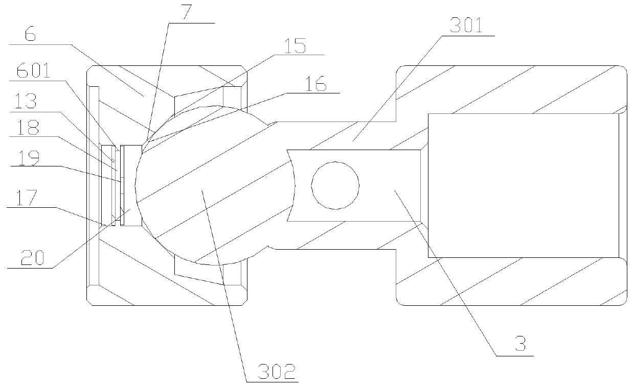
[0034] like Figure 1 to Figure 4 As shown, a fuel injector includes a fuel injector 2, a valve core assembly 3, a valve seat 6 and a first baffle 13. The fuel injector 2 is provided with a fuel injection hole 4, and the valve core assembly 3 It includes a valve core 301 and a sealing ball 302 connected together, the sealing ball 302 is used to seal the oil injection hole 4, and the valve seat 6 is arranged in the oil injection nozzle 2 near the end of the oil injection hole 4 , the valve seat 6 and the sealing ball 302 form an oil passage 17 along the direction that the sealing ball 302 approaches the oil injection hole 4, the first blocking piece 13 is fixedly arranged in the oil passage 17, and It includes a second baffle 19, the second baffle 19 is arranged in the oil passage 17, and both the first baffle 13 and the second baffle are in sealing connection with the valve seat 6;

[0035] The second blocking piece 19 is arranged on the side of the first blocking piece 13 cl...

Embodiment 2

[0048] Embodiment 2: be the preferred embodiment of embodiment 1,

[0049] like Figure 1 to Figure 4 Shown: a fuel injector,

[0050] Comprising a fuel injection nozzle 2, a valve core assembly 3, a valve seat 6 and a first stopper 13, the fuel injection nozzle 2 is provided with an oil injection hole 4, and the valve core assembly 3 includes a valve core 301 and a A sealing ball 302, the sealing ball 302 is used to seal the fuel injection hole 4, the valve seat 6 is arranged in the fuel injection nozzle 2 near the end of the fuel injection hole 4, the valve seat 6 and the The sealing ball 302 forms an oil passage 17 along the direction that the sealing ball 302 is close to the oil injection hole 4, the first blocking piece 13 is fixedly arranged in the oil passage 17, and also includes a second blocking piece 19, the The second blocking piece 19 is arranged in the oil passage 17, and both the first blocking piece 13 and the second blocking piece are in sealing connection w...

Embodiment 3

[0081] Embodiment 3: be the preferred embodiment of embodiment 2

[0082] The difference with embodiment 1 is:

[0083] Both the first baffle 13 and the second baffle 19 are welded and hermetically connected to the raised portion 601 on the valve seat 6;

[0084]Preferably, the first blocking piece 13 and the second blocking piece 19 are respectively sealed and welded to the left and right sides of the raised portion 601, so that the first blocking piece 13, the second blocking piece 19 and the raised portion 601 form a buffer condensation chamber 18. The overflow cavity 20 is formed by the second blocking plate 19, the inner wall of the oil passage 17 and the sealing ball 302.

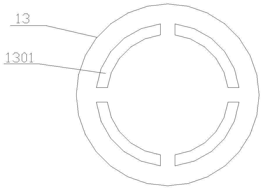
[0085] like figure 2 As shown, the injection hole 1301 on the first blocking plate 13 is an arc-shaped hole around the center of the first blocking plate 13;

[0086] like image 3 As mentioned above, the opening 1901 in the center of the second blocking piece 19 is a circular hole;

[0087] Bot...


PUM


Abstract

The invention discloses an oil injector. The oil injector comprises an oil injection nozzle, a valve core assembly, a valve seat and a first baffle piece. Oil injection holes are formed in the oil injection nozzle. The valve core assembly comprises a valve core and a sealing ball which are connected integratedly, the valve seat and the sealing ball form an oil channel in the direction of the sealing ball close to the oil injection hole, and the first baffle piece is fixedly arranged in the oil channel. A second baffle piece is further included and arranged in the oil channel, and the first baffle piece and the second baffle piece are connected with the valve seat in a sealing mode. The second baffle piece is arranged the side, near the sealing ball, of the first baffle piece, a buffer condensation cavity is formed between the first baffle piece and the second baffle piece, an overflow cavity is formed between the second baffle piece and the sealing ball, at least two injection holes are formed in the first baffle piece, and an opening is formed in the second baffle piece. The invention further discloses an engine, and the engine comprises the oil injector and a gas inlet manifold.According to the oil injector and the engine, the sealing effect of the oil injection holes can be improved, the leakage of air flow is prevented, the blockage caused by electrostatic accumulation isprevented, and the movement contact surface of the valve core assembly of the oil injector is prevented from bonding oil mud and the other matters.

Description

technical field [0001] The invention relates to the technical field of fuel injectors, in particular to a fuel injector and an engine. Background technique [0002] After a large number of tests, it was found that the combustion temperature of the methanol fuel engine is higher, and the moisture produced by the combustion is more than that of the gasoline combustion state. A large amount of high-temperature water vapor mixed with oil vapor enters the crankcase and then passes through the oil-gas separation system. The oil-gas separation effect is Heat exchange, higher temperature, excessive combustion moisture vapor and oil vapor are condensed through oil-air separation, making it exceed the heat exchange capacity of the engine oil-air separation system, so the crankcase gas mixed with oil vapor and water vapor enters the intake air When the manifold participates in the combustion process, it is unavoidable to avoid the influence of pollution on the components in the contact...

Claims


Application Information

Patent Timeline
Patent Type & Authority Applications(China)
IPC IPC(8): F02M61/16F02M61/18
Inventor 李书福缪英超金先扬
Owner ZHEJIANG GEELY HOLDING (GROUP) CO LTD
Learn More