Resistor spot welding method under action of controllable rotating magnetic field

A rotating magnetic field and resistance spot welding technology, applied in resistance welding equipment, welding equipment, metal processing equipment, etc., can solve the problems of uncontrollable, single magnetic field movement mode, poor mechanical properties of joints, etc. The effect of grain refinement is obvious and the welding quality is improved

Active Publication Date: 2019-05-17
HARBIN INST OF TECH AT WEIHAI
View PDF12 Cites 7 Cited by
  • Summary
  • Abstract
  • Description
  • Claims
  • Application Information

AI Technical Summary

Problems solved by technology

[0004] 2) There is a large internal stress, resulting in relatively poor mechanical properties of the joint
However, the device used to generate the magnetic field in the paper has certain limitations:
[0011] 2) The movement mode of the magnetic field is single, and it is radially tiled on the surface of the workpiece. The magnetic field cannot be rotated, and the size, direction, and frequency of the rotation cannot be adjusted.

Method used


Image

  • Resistor spot welding method under action of controllable rotating magnetic field
  • Resistor spot welding method under action of controllable rotating magnetic field

Examples


Embodiment

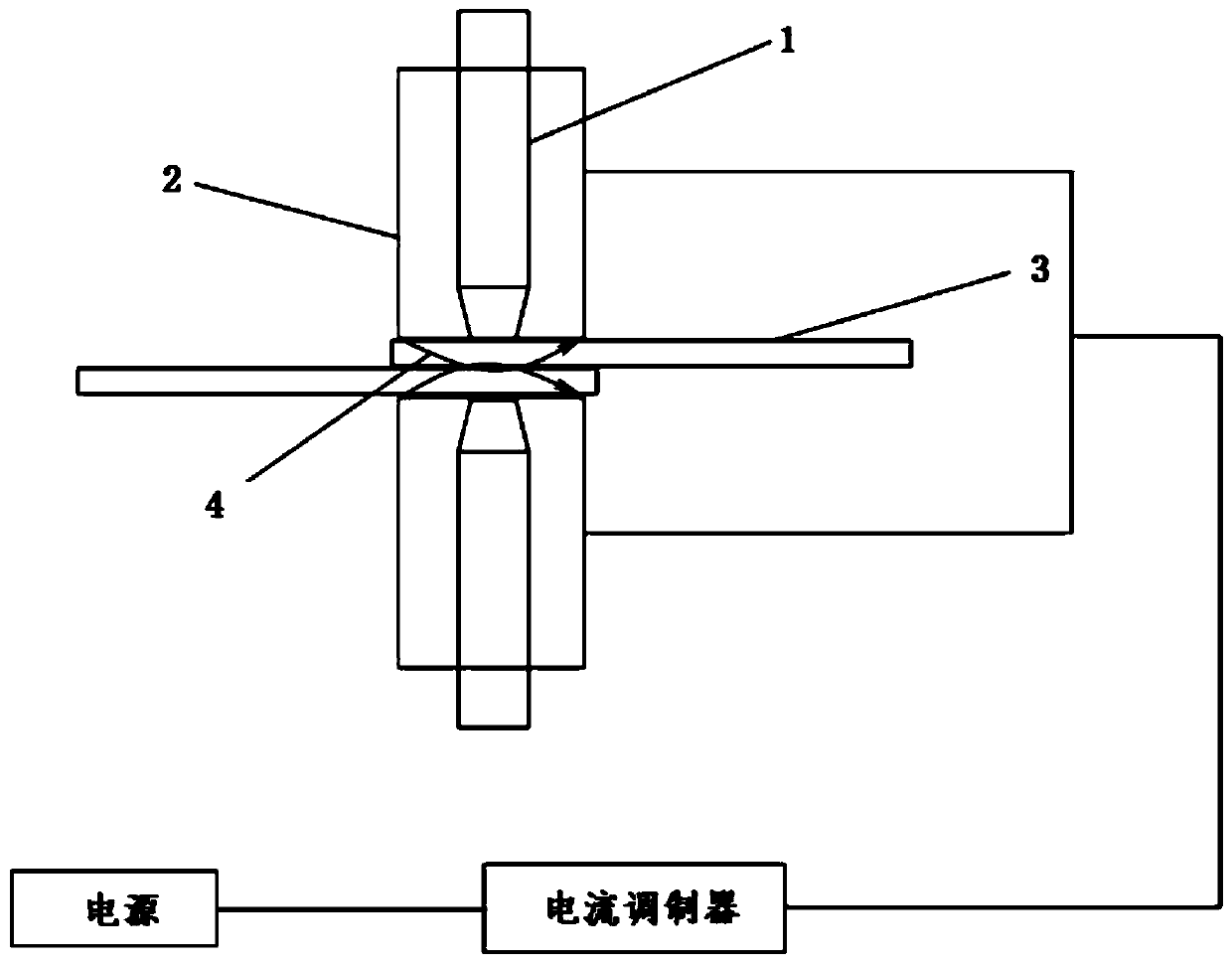
[0047] Example: Combined figure 1 with figure 2 , the resistance spot welding method under the action of a controllable rotating magnetic field of this embodiment is further elaborated:

[0048] First: For different welding conditions, use different welding fixtures to clamp and fix the workpiece to be welded. The fixture should ensure that the position of the welding spot can be positioned, and the welding current can flow through the welding workpiece from the end face of the electrode longitudinally during the welding process;

[0049] Second: adjust the welding parameters of the resistance welding machine, preset the welding current, welding time, and start the cooling water cycle;

[0050] Again: when the welding system is turned on, turn on the magnetic field generator, set the frequency, strength, and phase of the exciting three-phase alternating current, and check the distribution and movement of the magnetic field in the simulation mode;

[0051] Again: check the a...


PUM

PropertyMeasurementUnit
thicknessaaaaaaaaaa

Abstract

The invention discloses a resistor spot welding method under the action of a controllable rotating magnetic field, belongs to the technical field of welding, and solves the problems that the resistorspot welding point strength is low, the tissue is large, the magnetic controlled resistor spot welding magnetic field direction is not parallel to a workpiece, and the stirring effect of Lorenz forceproduced under the magnetic field action depends on the conduction current. The resistor spot welding method comprises the specific steps that a welding workpiece is clamped and fixed, the welding parameters of a resistor welding machine are adjusted, when a welding system is started, a magnetic field generation device is opened, and the frequency, intensity, phase of excitation three-phase AC areset; and an air pressure system is checked to determine the welding position, the magnetic field generation device is started to send the signal to the welding system, the welding system monitors thesignal of a magnetic field monitoring system, the welding system is started for welding, the welding process is finished, an electrode head is lifted, and the magnetic field generation device is closed. The resistor spot welding method can be used for metal plate resistor spot welding in the industrial field, the grain refinement effect of the fusing core area of a joint after welding is obvious,the tensile strength is improved, and the welding quality is improved.

Description

technical field [0001] The invention relates to a resistance spot welding method, in particular to a resistance spot welding method under the action of a controllable rotating magnetic field, and belongs to the field of welding technology. Background technique [0002] Resistance spot welding is a traditional welding method widely used in vehicle structure welding, but in the actual resistance welding process, there are the following problems: [0003] 1) The welding area is small, the cooling speed of the weld nugget area is fast, and the grains are coarse. [0004] 2) There is a large internal stress, resulting in relatively poor mechanical properties of the joint. [0005] In order to solve the above problems, inspired by electromagnetic metallurgy, it is possible to stir the nugget area of ​​the resistance spot welding joint by extending the electromagnetic stirring principle in the metallurgical industry to the process of resistance spot welding. At the same time, ins...

Claims


Application Information

Patent Timeline
Patent Type & Authority Applications(China)
IPC IPC(8): B23K11/11B23K11/36
Inventor 杨海峰周利刘煜纯胡国鹏周威佳赵洪运祁喆许欣欣郭孜颂王宇轩丁彦华许子彦
Owner HARBIN INST OF TECH AT WEIHAI
Why Eureka
Try Eureka