Manual welding speed detection equipment

A speed detection, manual welding technology, applied in welding equipment, arc welding equipment, metal processing equipment, etc., can solve the problems of inaccurate, time-consuming, and difficult to directly detect welding speed, and achieve simple structure, strong anti-interference, high precision high effect

Active Publication Date: 2020-09-22
HOHAI UNIV CHANGZHOU
View PDF5 Cites 0 Cited by
  • Summary
  • Abstract
  • Description
  • Claims
  • Application Information

AI Technical Summary

Problems solved by technology

There are also literatures that use the method of installing a roller on the welding torch to convert the welding speed into the rotational speed of the roller, and then display it through the speedometer. The accuracy of the result obtained in this way is affected by the running surface of the roller, and the overall device is not light and stable enough.
In the manual welding process, it is difficult to directly detect the welding speed due to the influence of the operator
In the traditional method, people usually divide the total length of a weld by the total welding time to roughly estimate the welding speed. This method is time-consuming, not accurate enough, and cannot directly obtain the value of the welding speed in real time. It needs to be improved

Method used


Image

  • Manual welding speed detection equipment
  • Manual welding speed detection equipment
  • Manual welding speed detection equipment

Examples


Embodiment Construction

[0028] The present invention will be further described below in conjunction with the accompanying drawings. The following examples are only used to illustrate the technical solution of the present invention more clearly, but not to limit the protection scope of the present invention.

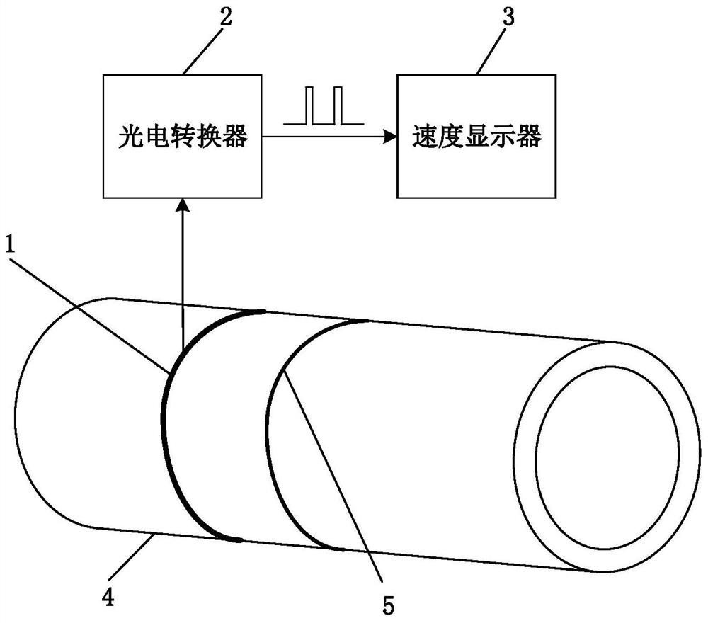
[0029] Such as figure 1 As shown, a manual welding speed detection device, the device includes an arc capture mechanism 1, a photoelectric converter 2 and a speed display 3;

[0030] The arc light capturing mechanism is fixed on the workpiece 4 to be welded parallel to the weld seam, and can be bent freely according to the shape of the weld seam 5. Its function is to capture the arc light incident by the arc perpendicular to the mechanism every time the arc moves a certain distance;

[0031] The photoelectric converter is used to convert the captured arc light signal into a pulse signal reflecting the welding speed;

[0032] The function of the speed display is to process the received pulse si...


PUM


Abstract

The invention discloses a manual-welding speed detecting device. The device includes an arc capturing mechanism, a photoelectric converter and a speed display, wherein the arc capturing mechanism parallels to a weld bead, is fixed to a workpiece to be welded, and is freely bent according to the shape of the weld bead; the functions of the arc capturing mechanism are that an electric arc moves a certain distance each time, the electric arc perpendicular to the mechanism produces an incident arc which is captured by the mechanism; the photoelectric converter is used to convert a captured arc signal into a pulse signal reflecting a welding speed; the functions of the speed display are that the received pulse signal is processed and the digital quantity of the welding speed in real time is displayed. According to the manual-welding speed detecting device, a photoelectric method is used; the device has simple structure, practicality and reliability; the mechanical structure of the device has flexibility; the problem that the welding speed cannot be detected in real time during the manual-welding process of the space weld and the all-position weld; and compared with a traditional methodof roughly estimating the welding speed, the device has the advantages of real time, digitization, high anti-interference and higher precision.

Description

technical field [0001] The invention relates to a manual welding speed detection device, which belongs to the technical field of real-time detection devices for manual welding speed. Background technique [0002] The welding speed has a great influence on the shape, appearance and internal quality of the weld. Obtaining an accurate value of the welding speed is helpful for the designer to formulate a more reasonable welding process. For automatic welding, the usual way to measure the welding speed is to use the encoder to detect the speed of the welding trolley, and the conversion will be displayed. There are also literatures that use the method of installing a roller on the welding torch to convert the welding speed into the rotational speed of the roller, and then display it through the speedometer. The accuracy of the result obtained in this way is affected by the running surface of the roller, and the overall device is not light and stable enough. In the manual welding ...

Claims


Application Information

Patent Timeline
Patent Type & Authority Patents(China)
IPC IPC(8): B23K9/095
Inventor 傅强陈志远朱雅琼吴家鑫田雪婷杨泽宇鲍孟程
Owner HOHAI UNIV CHANGZHOU
Why Eureka
Try Eureka