
Battery case for quickly replacing battery

A battery box and battery technology, which is applied to battery pack components, circuits, electrical components, etc., can solve the problems of laborious battery removal, inconvenient battery removal, and inability to align the positive and negative electrodes of the battery. sequence and convenient effects

Inactive Publication Date: 2019-05-14
ZHENGZHOU UNIV OF IND TECH
View PDF0 Cites 4 Cited by
  • Summary
  • Abstract
  • Description
  • Claims
  • Application Information

AI Technical Summary

Problems solved by technology

[0003] However, the batteries in the battery box device are generally deep in the battery box. The battery box is generally built into the inside of the electrical appliance, and it is generally very inconvenient to take out the battery. In order to facilitate the removal of the battery from the battery box on the market, a traction line is provided at the bottom of the battery box. When the pull wire is generally used, it is necessary to place the end of the wire outside the battery box, and then press the battery into the battery box along the line, but in many cases, the head of the pull wire falls directly into the bottom of the battery box, so that the battery cannot be pulled out through the pull wire. It is very laborious to take out the battery. At present, there are many battery boxes with elastic buckles on the market, but they are mostly used in the field of lithium batteries. As a result, the positive and negative poles of the battery cannot be aligned, and when the battery is taken out, the elastic device is easy to bounce the battery out of order. For this type of dry battery, there is a lack of convenient and efficient battery removal device on the market. Therefore, to solve this problem, we need a A kind of battery case device that can take out the battery conveniently

Method used


Image

  • Battery case for quickly replacing battery
  • Battery case for quickly replacing battery
  • Battery case for quickly replacing battery

Examples


Embodiment 1

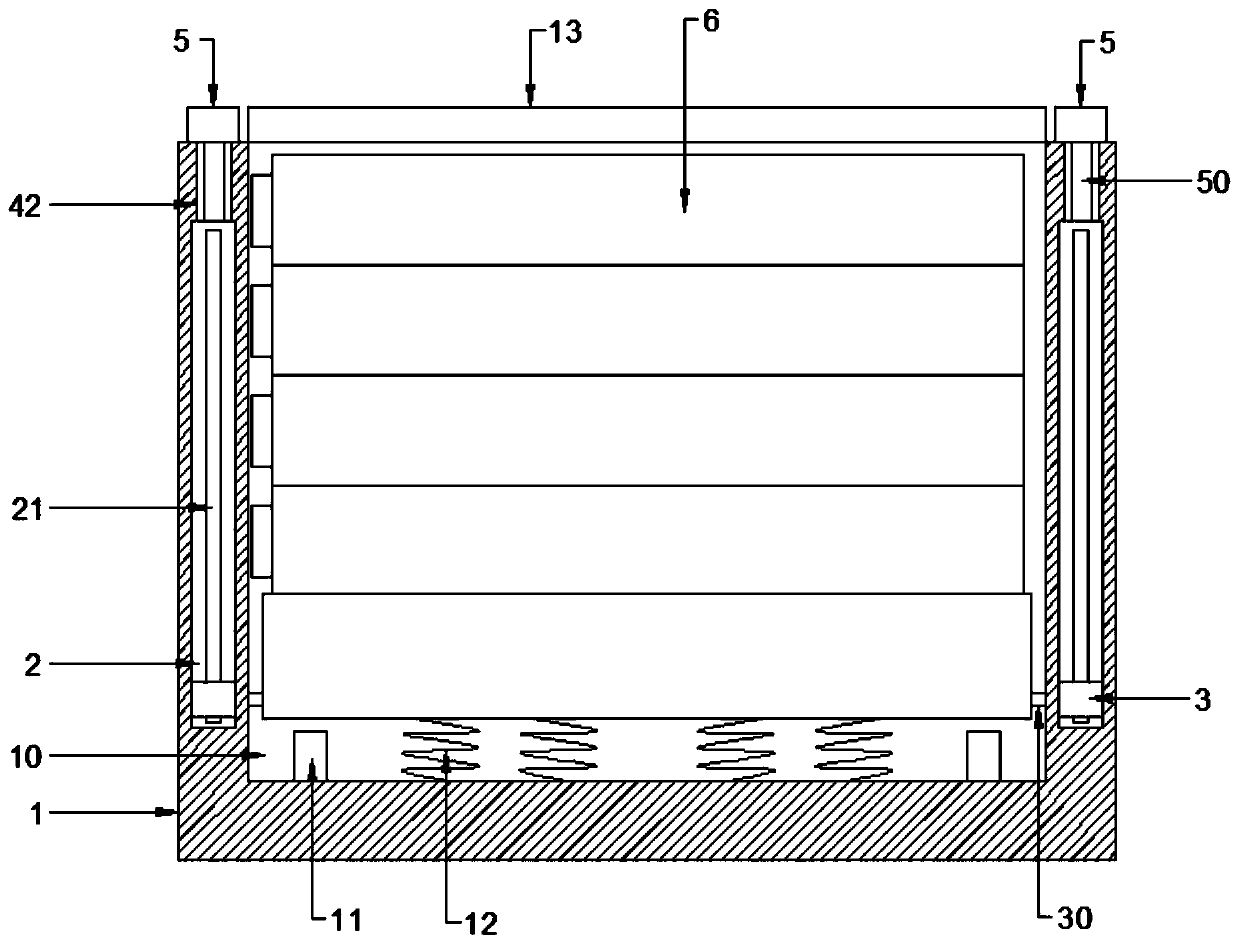
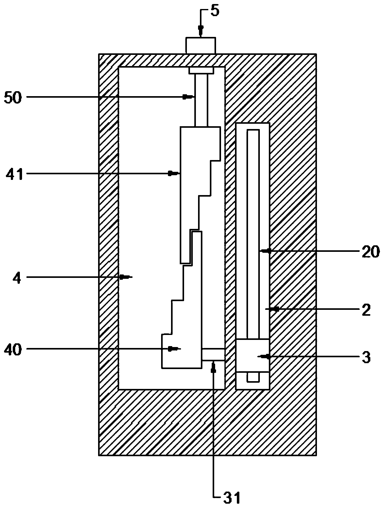
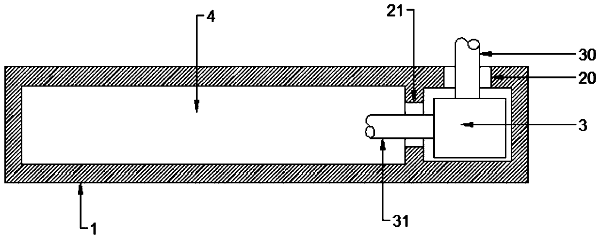
[0023] see Figure 1~6 , in an embodiment of the present invention, a battery box for quick battery replacement includes a battery box 1, a battery cavity 10 is provided in the battery box 1, and a plurality of batteries 6 are vertically placed in the battery cavity 10, the The top of the battery cavity 10 is provided with a box cover 13, and the bottom of the battery cavity 10 is provided with a support plate 14 supporting the battery 6, and the support plate 14 is fixed on the bottom surface of the battery cavity 10 by a plurality of support springs 12 with upward elastic forces. A gear cavity 4 is opened in the left and right inner walls of the battery box 1, and a supporting gear block 40 and an adjusting gear block 41 are provided in the gear cavity 4, and the supporting gear block 40 and the adjusting gear block 41 are interlocked. The adjustment gear block 41 is set as a ladder type, and the support gear block 40 is arranged opposite to the stepped surface of the adjust...

Embodiment 2

[0031] The difference between this embodiment and embodiment 1 is:

[0032] The adjusting block 5 is provided with a tightening device to keep the sliding position of the adjusting block 5 fixed. The tightening device includes a fixed screw hole 52 and a fixed thread head 53. The fixed screw hole 52 is opened on the bottom surface of the adjusting block 5 , the fixed threaded head 53 is set on the top rod wall of the connecting rod 50, and the adjusting block 5 is screwed on the top of the connecting rod 50 through the fixed screw hole 52 and the fixed threaded head 53.

[0033] Working principle of the present invention: the set screwing device can screw down the adjusting block 5 when the position of the adjusting block 5 needs to be fixed, so as to ensure that the adjusting block 5 can be tightly covered on the top opening side of the adjusting slide 42, Therefore, it is ensured that the position of the adjustment gear block 41 connected to the bottom end of the sheet conne...


PUM


Abstract

The invention discloses a battery case for quickly replacing a battery, comprising a battery case, wherein the bottom of the battery chamber is provided with a support plate for supporting the battery, the support plate is fixed on the bottom surface of the battery chamber by a plurality of elastic upward support springs, gear chambers are provided in the inner walls of the left and right sides ofthe battery case, the gear chambers are internally provided with a support gear block and an adjusting gear block which are engaged with each other, the adjusting gear block is connected to adjustingblocks disposed on both sides of the top surface of the battery case by an adjusting device, the adjusting gear block is slidably locked in the gear chambers by the adjusting device sliding back andforth, and the support gear block is slidably locked in the gear chambers by the sliding device sliding up and down. The invention can automatically discharge the batteries in the battery case one byone in order by the set adjusting blocks, which solves the inconvenience of taking out multiple batteries in the battery box on the one hand, and greatly facilitates the pick-and-place of the batteries without causing disordered or uncontrollable battery removal on the other hand.

Description

technical field [0001] The invention relates to the field of battery boxes, in particular to a battery box for quickly replacing batteries. Background technique [0002] The battery box is mainly composed of a box body and a cover body. The box body and the cover body are combined to form a hollow cavity that can accommodate the battery. The conductor used to realize the electrical connection between the battery and the power supply terminal of the electrical appliance is arranged in the hollow cavity. The box can be assembled with various batteries such as ordinary dry batteries, lithium batteries or other rechargeable batteries. Electrical and other fields. [0003] However, the batteries in the battery box device are generally deep in the battery box. The battery box is generally built into the inside of the electrical appliance, and it is generally very inconvenient to take out the battery. In order to facilitate the removal of the battery from the battery box on the ma...

Claims


Application Information

Patent Timeline
Patent Type & Authority Applications(China)
IPC IPC(8): H01M2/10H01M50/247H01M50/256
CPCY02E60/10
Inventor 王飞
Owner ZHENGZHOU UNIV OF IND TECH
Learn More