
Air cap resistance calculation method

A technology of resistance calculation and air cap, applied in the field of boilers, can solve the problems of large resistance coefficient of air distribution plate air cap and large energy consumption of fans, so as to improve the gas-solid two-phase flow field, reduce pollutant emissions, and improve fuel utilization rate. Effect

Pending Publication Date: 2019-05-14
哈尔滨哈锅锅炉容器工程有限责任公司
View PDF3 Cites 0 Cited by
  • Summary
  • Abstract
  • Description
  • Claims
  • Application Information

AI Technical Summary

Problems solved by technology

[0004] In order to solve the problem that the resistance coefficient of the air distribution plate is selected according to experience when designing the air distribution plate of the current circulating fluidized bed boiler, the resistance coefficient of the air distribution plate hood is relatively large, resulting in large energy consumption of the fan, and the present invention provides A Calculation Method of Wind Hood Resistance

Method used


Image

  • Air cap resistance calculation method
  • Air cap resistance calculation method
  • Air cap resistance calculation method

Examples


specific Embodiment approach 1

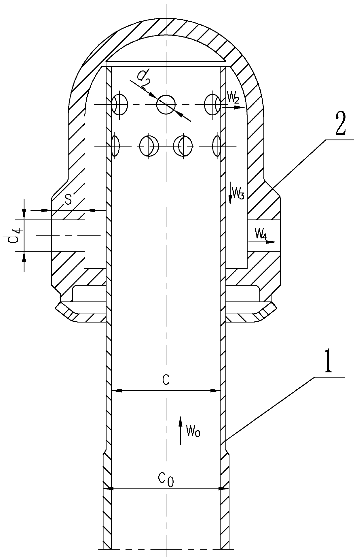
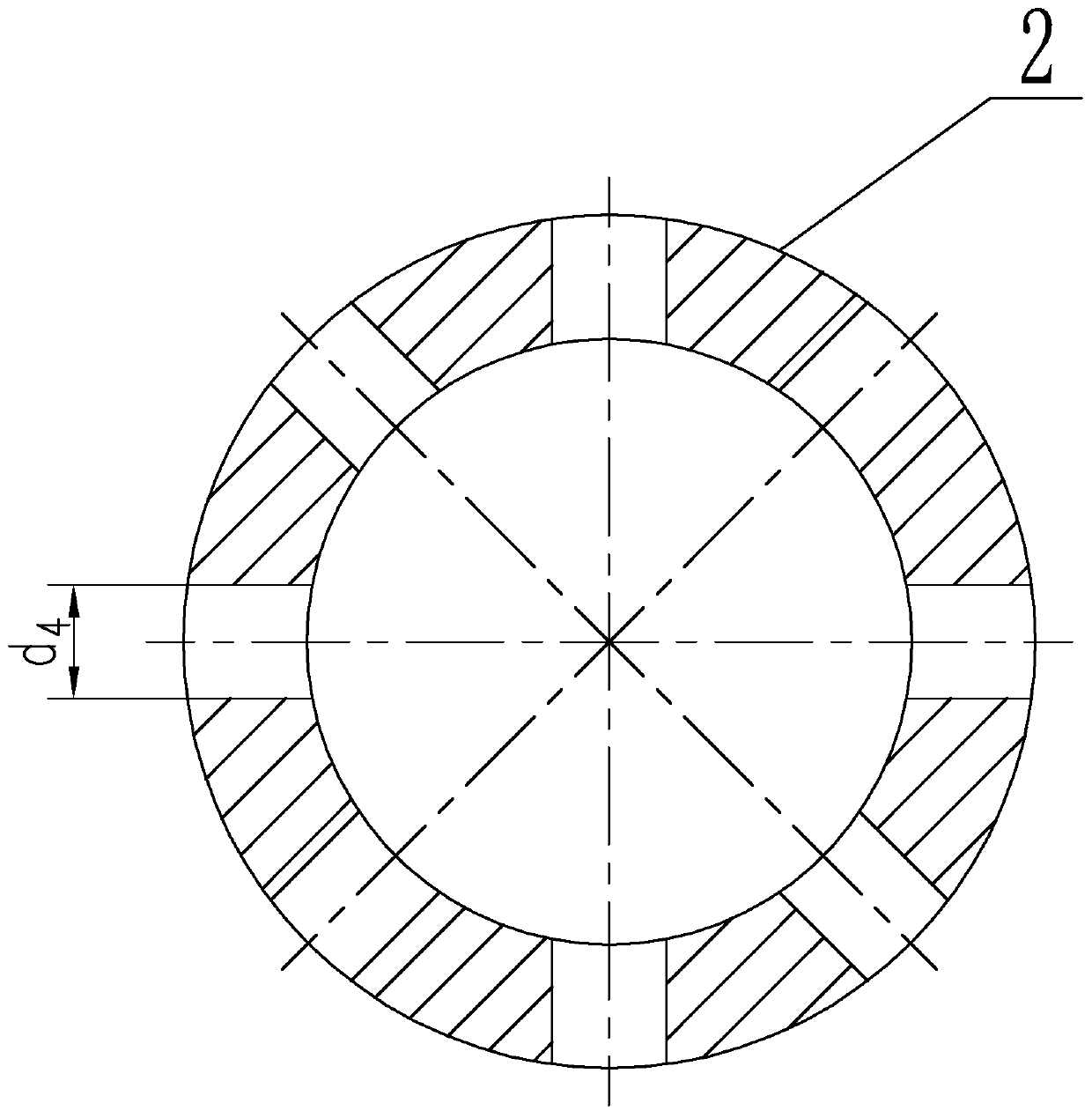
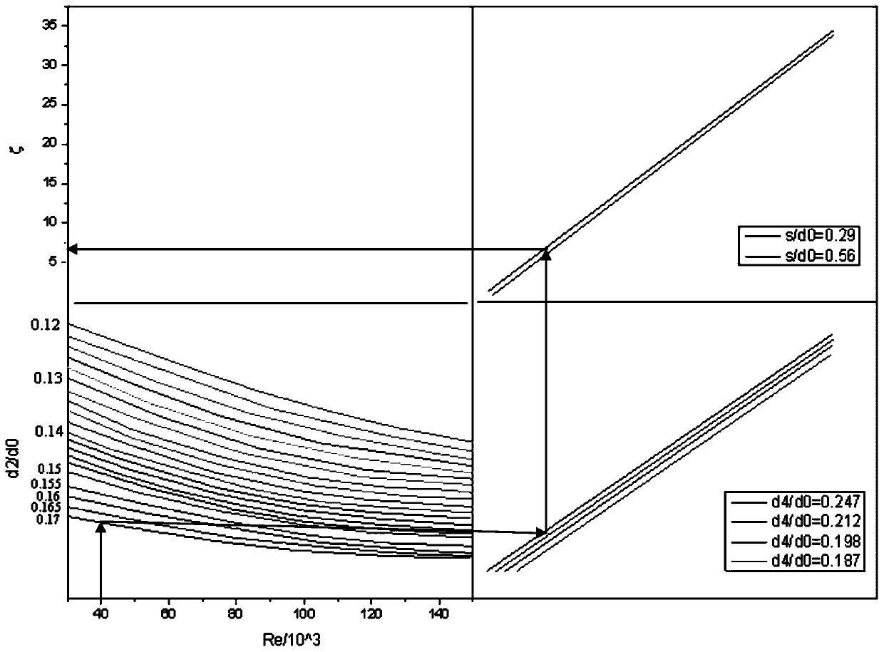
[0019] Specific implementation mode one: combine Figure 1-Figure 3 To illustrate this embodiment, this embodiment includes the following steps:

[0020] 1. The resistance of hot air flowing through a single hood is equivalent to the resistance generated by the hot air in the air inlet pipe 1 on a single hood, and the resistance coefficient of a single hood is equivalent to the resistance coefficient of the flow velocity of the air inlet pipe 1 on a single hood, that is

[0021] ΔP=ζ×ρ×W 2 0 / 2

[0022] Among them, ΔP is the resistance of a single hood, the unit is Pa; ζ is the resistance coefficient of a single hood; ρ is the density of the fluid in the hood, the unit is kg / m 3 ;W 0 is the wind speed in the air inlet pipe 1, the unit is m / s;

[0023] 2. Select the Reynolds number Re first, and select the appropriate Reynolds number according to the viscosity of the fluid, the equivalent diameter of the fluid flow and the flow rate W of the fluid, namely

[0024] Re=W×d / ...

specific Embodiment approach 2

[0029] Specific implementation mode two: combination figure 1 To illustrate this embodiment, the wind speed W in the air inlet duct 1 of this embodiment 0 It is 35-55m / s.

[0030] The relationship curve between the drag coefficient and the various structural dimensions of the wind cap is suitable for the wind speed W in the air inlet pipe 1 0 The wind speed is between 35-55m / s.

[0031] Other compositions and connections are the same as in the first embodiment.

specific Embodiment approach 3

[0032] Specific implementation mode three: combination figure 1 To illustrate this embodiment, the wind speed W of the air outlet in the air inlet pipe 1 of this embodiment 2 It is 45-60m / s.

[0033] The relationship curve between the drag coefficient and the various structural dimensions of the wind cap is suitable for the wind speed W of the air outlet in the air inlet pipe 1 2 The wind speed is between 45-60m / s.

[0034] Other compositions and connections are the same as those in the second embodiment.


PUM

PropertyMeasurementUnit
Resistanceaaaaaaaaaa

Abstract

The invention discloses an air cap resistance calculation method, belongs to the technical field of boilers, and aims to solve the problem that when an air distribution plate of an existing circulating fluidized bed boiler is designed, the resistance coefficient of the air distribution plate is selected according to experience, so that the resistance coefficient of the air cap of the air distribution plate is large, and the energy consumption of a fan is large. The method comprises the following steps of: 1, enabling resistance of a single hood to be equivalent to resistance corresponding to flow velocity in an air inlet pipe; the resistance coefficient is equivalent to the resistance coefficient corresponding to the flow velocity of the air inlet pipe; firstly, selecting a Reynolds numberRe; selecting a proper Reynolds number according to the viscosity of the fluid, the equivalent diameter of the fluid flow and the flow velocity W of the fluid; the resistance coefficient is determined on the relation curve of the wind cap resistance coefficient and the wind cap structure size according to the Reynolds number, and finally the resistance of the single wind cap is calculated according to the determined resistance coefficient of the single wind cap, the wind speed in the air inlet pipe and the density of fluid in the wind cap. The method is suitable for calculating the resistanceof the single hood on the air distribution plate of the circulating fluidized bed boiler.

Description

technical field [0001] The invention relates to the technical field of boilers, in particular to a method for calculating wind cap resistance. Background technique [0002] my country's circulating fluidized bed boiler was the first to use ALSTOM technology. With its continuous research and exploration, my country has made its own improvement and development. my country's circulating fluidized bed boiler technology is relatively mature and ranks among the world's advanced levels. In recent years, the number and stand-alone capacity of circulating fluidized bed boilers in my country have been developing rapidly, and there are more opportunities to go to the world. However, with the development of the national economy, energy waste is becoming more and more serious, and the country is also trying its best to promote the implementation of energy conservation and emission reduction policies. In order to comply with national policies, we have been looking for breakthroughs in the...

Claims


Application Information

Patent Timeline
IPC IPC(8): G06F17/50
Inventor 秦蓓沈兆强朱亮高傲
Owner 哈尔滨哈锅锅炉容器工程有限责任公司
Learn More