Lens driving apparatus, photographing module and electronic device
A lens drive device and lens technology, applied in focusing devices, installation, optics, etc., can solve the problems of limited production efficiency and manufacturing pass rate of lens drive devices
- Summary
- Abstract
- Description
- Claims
- Application Information
AI Technical Summary
Problems solved by technology
Method used
Image

Examples
no. 1 example
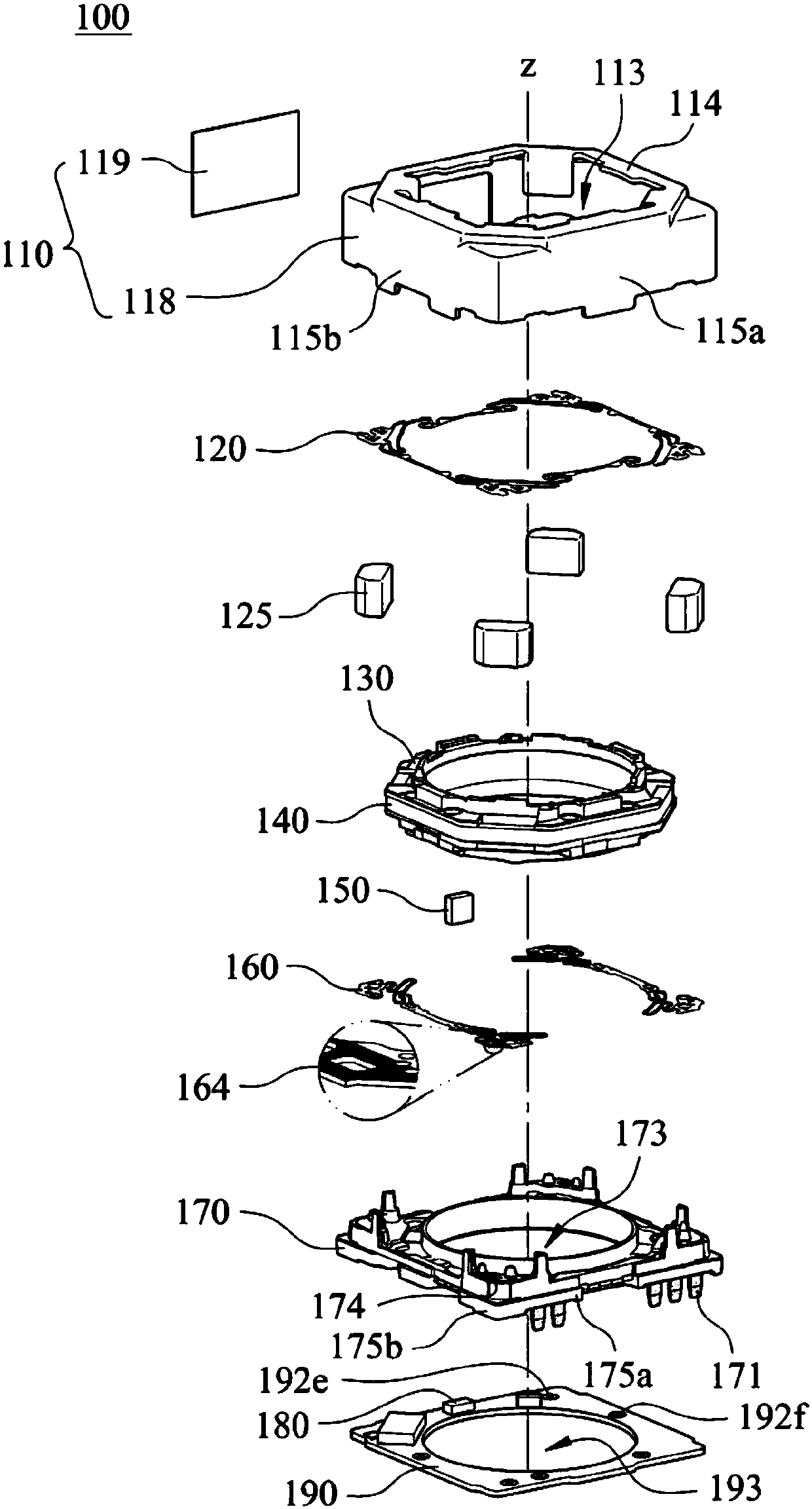
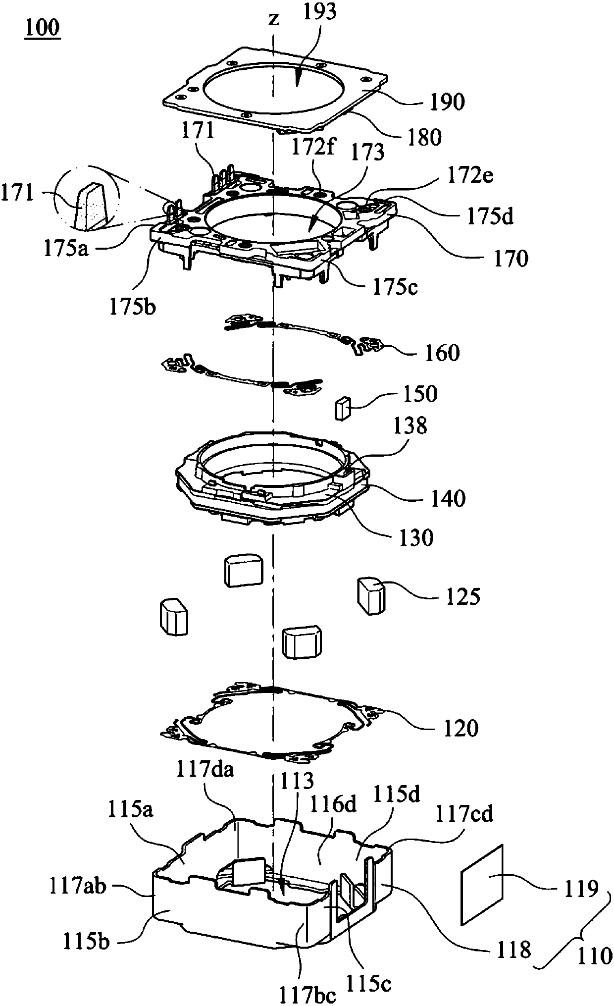
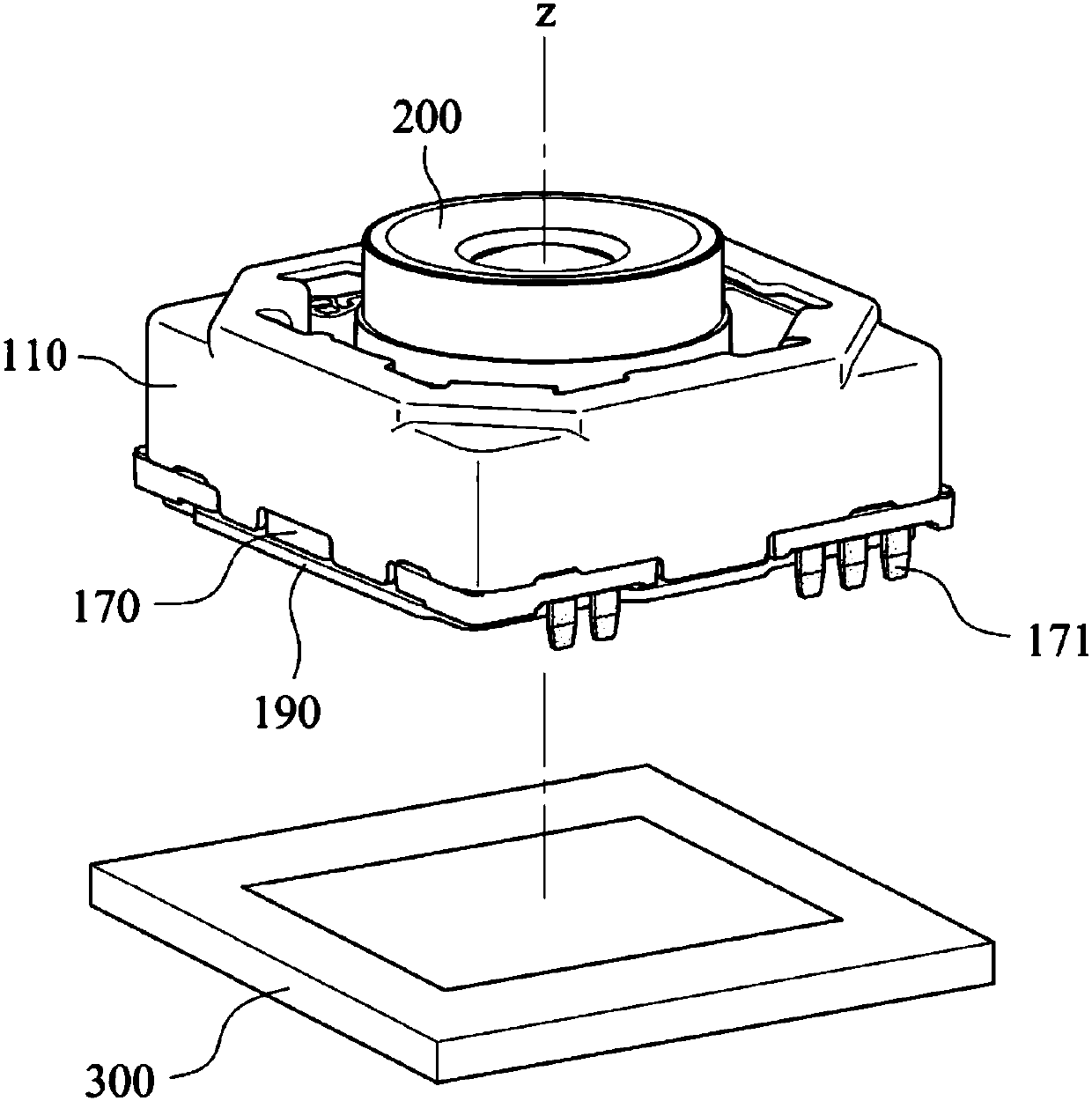
[0067] With reference Figure 1 to Figure 3 , figure 1 An exploded view showing the lens driving device 100 according to the first embodiment of the present invention, figure 2 Another exploded view showing the lens driving device 100 of the first embodiment, image 3 A schematic diagram of the lens driving device 100, the lens 200, and the electronic photosensitive element 300 of the first embodiment is shown. Depend on Figure 1 to Figure 3It can be seen that the lens driving device 100 is used to drive the lens 200, and the lens driving device 100 includes a base 170, a metal casing 110, a carrier 130, at least one sensing magnet 150, a circuit board 190, at least one position sensing element 180, a coil 140 and At least three drive magnets 125 .
[0068] Depend on image 3 It can be seen that the lens 200 is assembled with the lens driving device 100, and the electronic photosensitive element 300 is used to receive the imaging light from the lens 200 and is arranged ...
no. 2 example
[0099] With reference Figure 7 and Figure 8 ,in Figure 7 A schematic diagram showing an electronic device 10 according to a second embodiment of the present invention, Figure 8 Another schematic diagram of the electronic device 10 in the second embodiment is shown, and Figure 7 and Figure 8 In particular, a schematic diagram of a camera in the electronic device 10 . Depend on Figure 7 and Figure 8 It can be seen that the electronic device 10 of the second embodiment is a smart phone, and the electronic device 10 includes a camera module 11 and an electronic photosensitive element 13, wherein the camera module 11 includes a lens driving device 14 and a lens 12 according to the present invention, and the lens 12 and the lens drive The carrier (not shown) of the device 14 is assembled, and the electronic photosensitive element 13 is disposed on the imaging surface (not shown) of the lens 12 to receive the imaging light from the lens 12 . Therefore, with good imagin...
no. 3 example
[0106] With reference Figure 10 , Figure 10 A schematic diagram of an electronic device 20 according to a third embodiment of the present invention is shown. Depend on Figure 10 It can be seen that the electronic device 20 of the third embodiment is a smart phone, and the electronic device 20 includes the camera modules 21, 71 and the corresponding electronic photosensitive elements (not shown in the figure). The camera module 21 includes a lens driving device 24 and a lens 22 . The lens 22 is assembled with a carrier (not shown) of the lens driving device 24 . The electronic photosensitive element is used to receive the imaging light from the lens 22 . The camera module 71 includes a lens driving device 74 and a lens 72 . The lens 72 is assembled with a carrier (not shown) of the lens driving device 74 . The electronic photosensitive element is used to receive imaging light from the lens 72 .
[0107] Furthermore, at least one of the lens driving devices 24, 74 is a len...
PUM
 Abstract
Description
Claims
Application Information
 - R&D
- Intellectual Property
- Life Sciences
- Materials
- Tech Scout
- Unparalleled Data Quality
- Higher Quality Content
- 60% Fewer Hallucinations
Browse by: Latest US Patents, China's latest patents, Technical Efficacy Thesaurus, Application Domain, Technology Topic, Popular Technical Reports.
© 2025 PatSnap. All rights reserved.Legal|Privacy policy|Modern Slavery Act Transparency Statement|Sitemap|About US| Contact US: help@patsnap.com