
Telescopic screed overlap welding die jig

A screed and telescopic technology, which is applied in the field of lap welding mold fixtures for telescopic screeds, can solve the problems of crushing workpieces, difficult positioning and pressing, and weak pressing.

Inactive Publication Date: 2019-05-10
合肥佳恩特机械制造有限公司
View PDF4 Cites 0 Cited by
  • Summary
  • Abstract
  • Description
  • Claims
  • Application Information

AI Technical Summary

Problems solved by technology

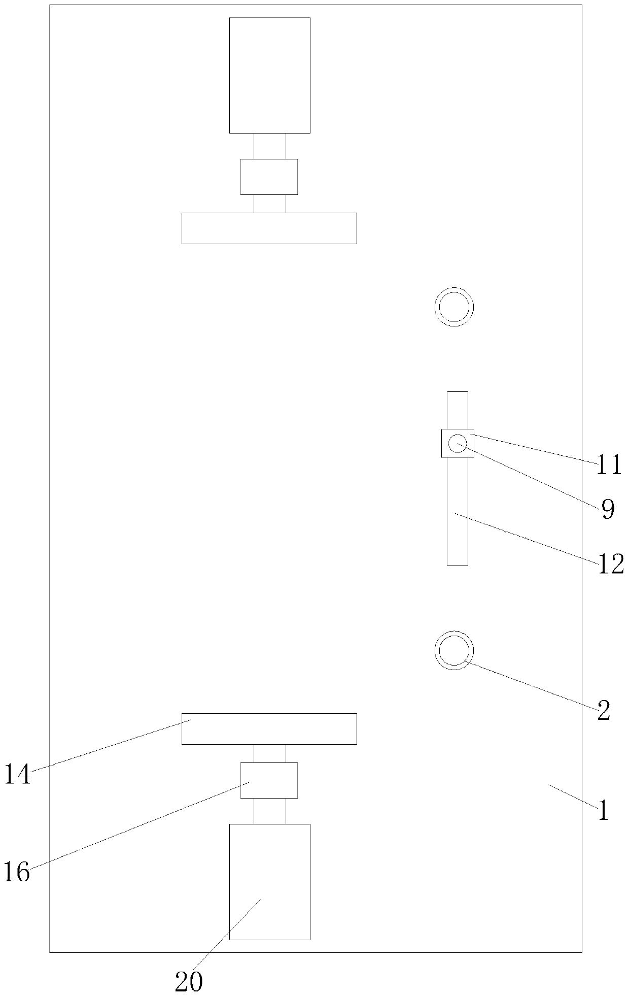
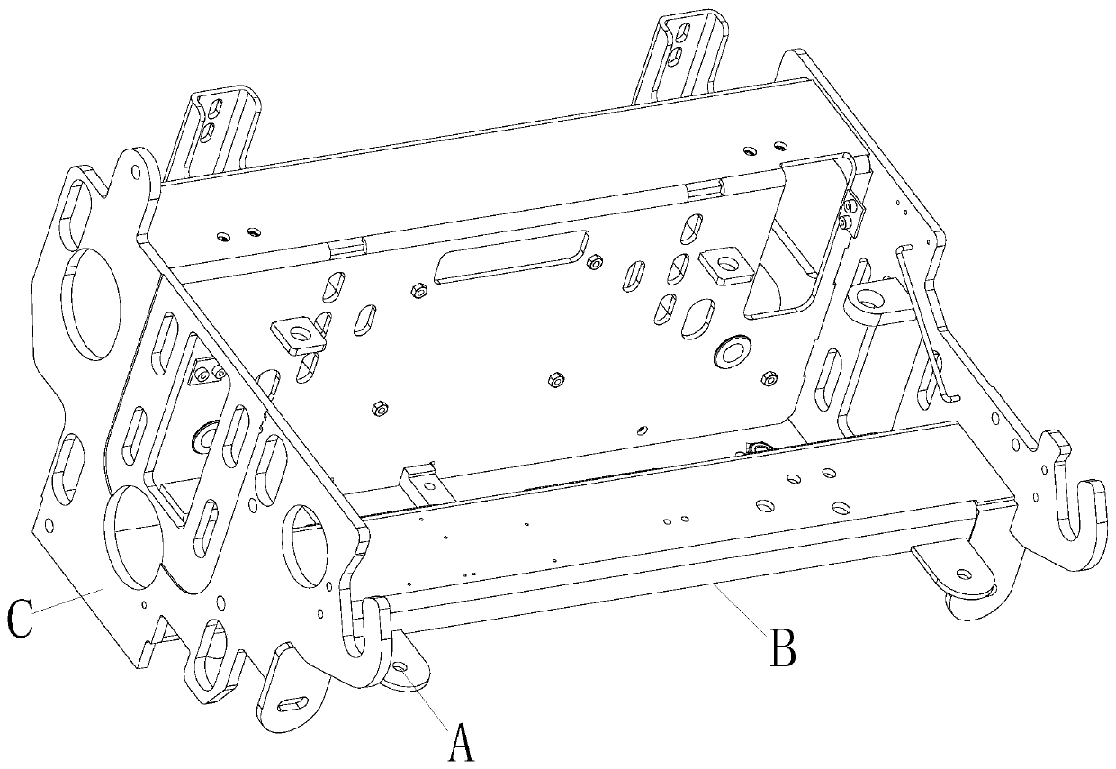
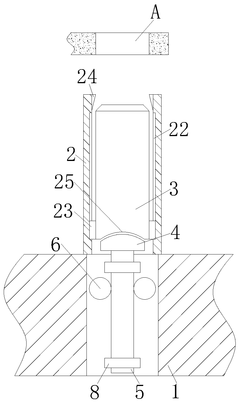
[0003] Since the screed is an irregular object, it is difficult to locate and compress it during processing. During lap welding, the workpiece needs to be positioned according to the positioning hole. However, when the existing fixture is positioned, the length of the positioning pin It is fixed, and the length cannot be adjusted. In actual processing, the workpiece may fall off from the positioning pin because the positioning pin is too short. In addition, the pressing force between the pressing block and the workpiece cannot be adjusted when the workpiece is pressed, which is easy to cause pressing. Not firm or the workpiece is crushed due to excessive local pressure

Method used


Image

  • Telescopic screed overlap welding die jig
  • Telescopic screed overlap welding die jig
  • Telescopic screed overlap welding die jig

Examples


Embodiment Construction

[0023] In order to make the technical means, creative features, goals and effects achieved by the present invention easy to understand, the technical solutions in the embodiments of the present invention will be clearly and completely described below in conjunction with the accompanying drawings in the embodiments of the present invention. Obviously, the The described embodiments are only some, not all, embodiments of the present invention. Based on the embodiments of the present invention, all other embodiments obtained by persons of ordinary skill in the art without creative efforts fall within the protection scope of the present invention.

[0024] In the description of the present invention, it should be noted that the orientation or positional relationship indicated by the terms "vertical", "upper", "lower" and "horizontal" are based on the orientation or positional relationship shown in the drawings, and are only for It is convenient to describe the utility and simplify ...


PUM


Abstract

The invention relates to the technical field of jigs, in particular to a telescopic screed overlap welding die jig, which comprises a bottom plate, a positioning barrel is arranged on the bottom plate, a positioning column is arranged in the positioning barrel, a push block is arranged below the positioning column, the push block is fixedly connected with a rack, and gears are meshed with the twosides of the rack. A supporting rod is arranged on the bottom plate, and the top of the supporting rod is rotationally connected with a U-shaped frame. A pressing block is further arranged on the bottom plate and fixedly connected with a connecting rod, the connecting rod is inserted into a sleeve, and a stud is arranged in the sleeve and fixedly connected with an output shaft of an air cylinder.According to the jig, a workpiece is coarsely positioned by moving the supporting rod to ensure that the positioning column can smoothly extend into the positioning hole, a motor drives the gears andthe rack to drive the positioning column to extend out, automatic positioning is achieved, the workpiece can be prevented from falling off the positioning column, the workpiece is pressed through theair cylinder, in this way, automatic pressing can be achieved, the pressing force of the pressing block on the workpiece can be adjusted by rotating the sleeve, and therefore the situations that pressing is not firm and the workpiece is damaged due to too large pressing force can be avoided.

Description

technical field [0001] The invention relates to the technical field of clamps, in particular to a retractable screed lap welding mold clamp. Background technique [0002] As the core working device of the asphalt paver, the screed directly determines the paving quality and performance of the machine. At present, the asphalt paver screeds at home and abroad all adopt the rectangular box structure welded by steel plates. Paver is a machine that evenly spreads asphalt mixture on the road base, and performs preliminary vibration and leveling. The vibration mechanism uses a screed and a vibrator installed in front of the screed, or a vibrating screed, or Both the vibrator and the vibrating screed are used at the same time to improve the vibration effect. The screed device is composed of a screed, a traction arm, a thickness regulator, a road crown regulator and a heater. The vibration screed device is equipped with a vibrator on the screed, which can play the role of vibration ...

Claims


Application Information

Patent Timeline
IPC IPC(8): E01C19/48
Inventor 陈鑫苏浩李鹏飞
Owner 合肥佳恩特机械制造有限公司
Learn More