
Polished wheel road roller for asphalt pavement

A technology of road rollers and smooth wheels, which is applied in the directions of roads, roads, and road repairs, can solve the problems of reducing the working efficiency of road rollers, easily sticking debris on the surface of smooth rollers, affecting the leveling of asphalt roads, etc. The effect of matching the range and reducing the degree of wear

Pending Publication Date: 2019-05-10
卢淑文
View PDF0 Cites 2 Cited by
  • Summary
  • Abstract
  • Description
  • Claims
  • Application Information

AI Technical Summary

Problems solved by technology

[0004] The invention provides a smooth wheel road roller for asphalt laying, which has the advantages of being convenient to protect the two smooth wheels and increasing the adaptation range of the equipment, and solves the problem that the existing road roller generally has two smooth wheels, and the smooth wheels in front of the headstock are both It is used for load bearing, crushing and preliminary rolling of asphalt, while the smooth wheel at the rear of the car is used to roll asphalt multiple times to ensure the smoothness of the asphalt road surface. Due to the different functions of the two light wheels, the former is often affected by The large impact force will cause serious impact and wear on the bearings on both sides of the smooth wheel, which greatly reduces the service life of the smooth wheel. During the rolling process of the latter, the surface of the smooth wheel is often easy to stick to debris, which has a great impact on the smooth wheel. The asphalt road is smooth, and the handles of the existing road rollers are all fixed structures, which have low adaptability, which greatly limits the operator's control of the road roller and reduces the working efficiency of the road roller.

Method used


Image

  • Polished wheel road roller for asphalt pavement
  • Polished wheel road roller for asphalt pavement
  • Polished wheel road roller for asphalt pavement

Examples


Embodiment Construction

[0023] The following will clearly and completely describe the technical solutions in the embodiments of the present invention with reference to the accompanying drawings in the embodiments of the present invention. Obviously, the described embodiments are only some, not all, embodiments of the present invention. Based on the embodiments of the present invention, all other embodiments obtained by persons of ordinary skill in the art without making creative efforts belong to the protection scope of the present invention.

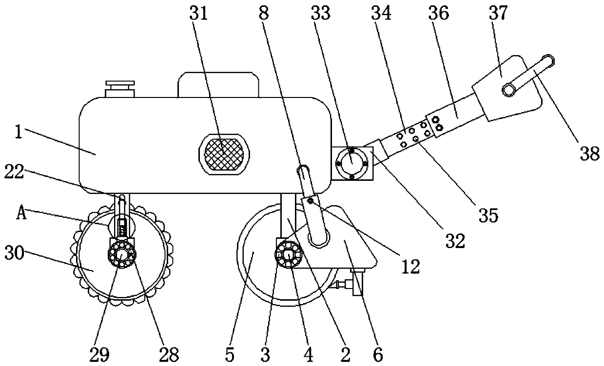
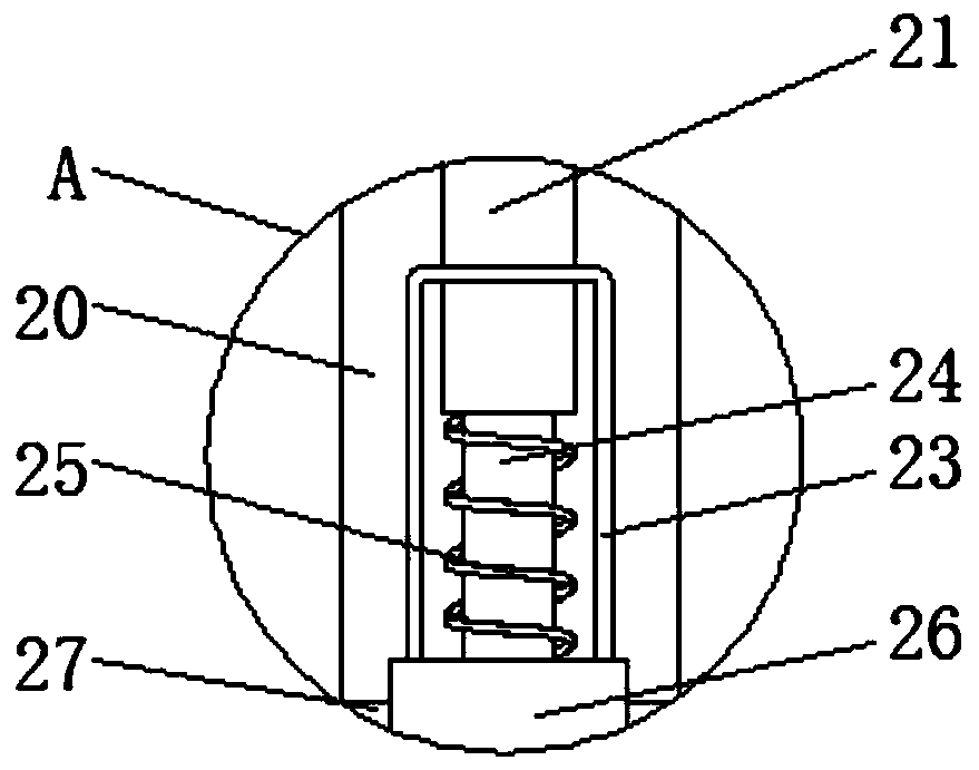
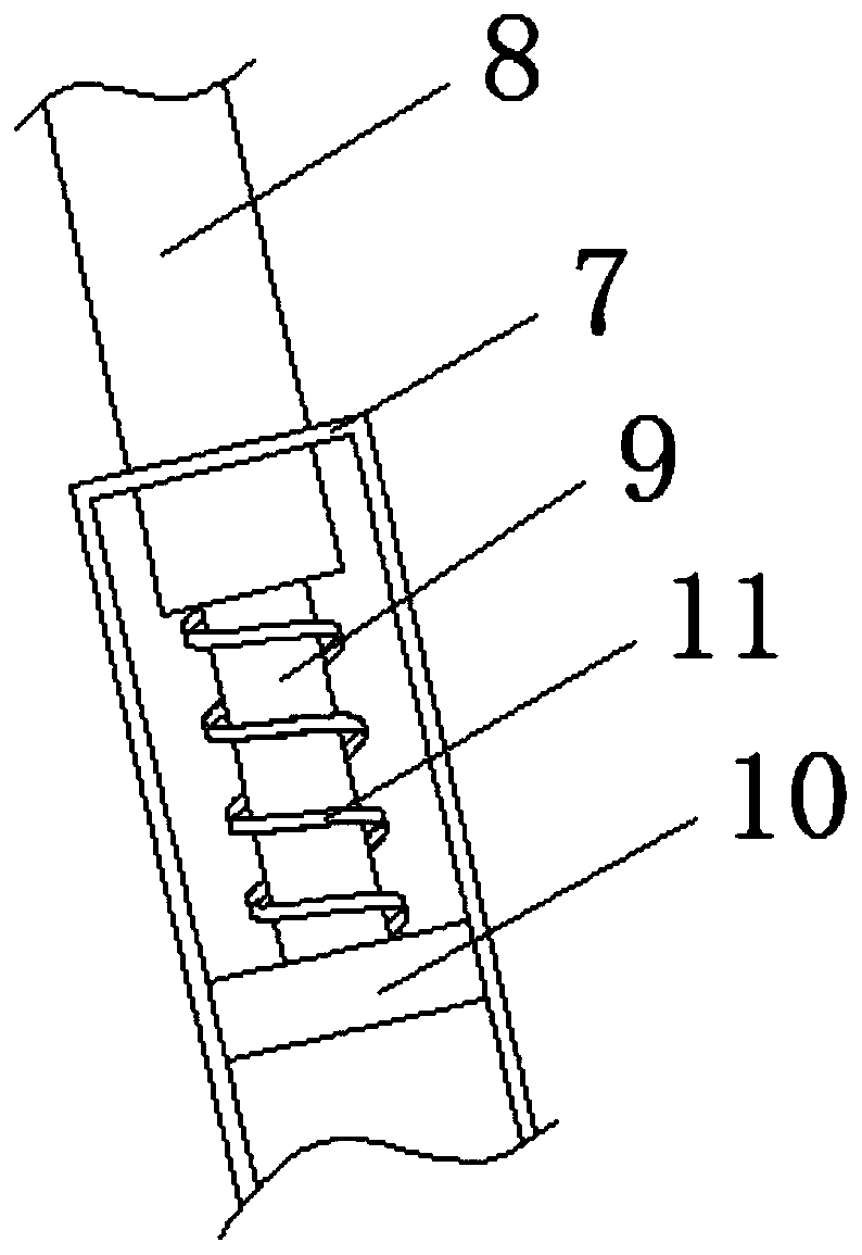
[0024] see Figure 1-4, a smooth wheel road roller for asphalt paving, comprising a body 1, a first stabilizer bar 2 is fixedly installed on the right end of the bottom surface of the body 1, a first bearing 3 is fixedly installed on the bottom end of the first stabilizer bar 2, and the first bearing 3 The inner fixed sleeve of the first roller 4 is equipped with the first roller 4, the inner and outer fixed sleeve of the first roller 4 is equipped with the fi...


PUM


Abstract

The invention relates to the technical field of road paving equipment and discloses a polished wheel road roller for asphalt pavement. The polished wheel road roller for asphalt pavement comprises a vehicle body, a first stabilizer bar is fixedly mounted at the right end of the bottom surface of the vehicle body, a first bearing is fixedly mounted at the bottom end of the first stabilizer bar, a first rolling shaft is fixedly sleeved with the first bearing, a first polished wheel located on the back face of the first stabilizer bar is fixedly sleeved with the interior and the exterior of the first rolling shaft, a stabilizer plate located on the front face of the first stabilizer bar is fixedly sleeved with the exterior of the first bearing, and a stabilizer sleeve rod is fixedly installedon the front face of the stabilizer plate. According to the polished wheel road roller for asphalt pavement, by arranging a movable rod at the top of a second bearing, the movable rod can be matchedwith a damping rod, so that vibration borne by the second bearing is relieved, large impact force frequently borne in the operation process of a second polished wheel is greatly reduced, the abrasiondegree between the second polished wheel and a second rolling shaft is reduced, and the service life of the equipment is guaranteed.

Description

technical field [0001] The invention relates to the technical field of road paving equipment, in particular to a smooth wheel road roller for asphalt paving. Background technique [0002] The road roller, also known as the soil compactor, is a kind of equipment for road construction. The road roller belongs to the category of road equipment in construction machinery. For practical operation, it can roll sandy, semi-cohesive and cohesive soil, roadbed stabilized soil and asphalt concrete pavement layer. The road roller is suitable for various compaction operations due to the gravity of the machine itself, so that the rolled layer will produce permanent deformation and compactness. . [0003] Existing road rollers generally have two smooth wheels. The smooth wheel at the front of the vehicle is used for load bearing, crushing and preliminary rolling of asphalt, while the smooth wheel at the rear of the vehicle is used for repeatedly rolling asphalt to ensure the smoothness of...

Claims


Application Information

Patent Timeline
IPC IPC(8): E01C19/23E01C19/24
Inventor 卢淑文
Owner 卢淑文
Learn More