
Natural-energy-driven wing-rudder linkage long-endurance twin-hull unmanned boat

An unmanned boat, long-endurance technology, applied in the directions of ships, motor vehicles, steering devices, etc., can solve the problems of inability to realize emergency stop of unmanned boats, unable to change the thrust distribution of the hull, and lack of swinging hydrofoil restraint devices, etc. Achieve the effect of increasing thrust, large heave and pitch amplitude, and increasing force application area

Active Publication Date: 2019-05-10
HARBIN ENG UNIV
View PDF11 Cites 13 Cited by
  • Summary
  • Abstract
  • Description
  • Claims
  • Application Information

AI Technical Summary

Problems solved by technology

[0005] In "A Biplane Wave-Propelled Long-range Unmanned Boat" proposed by Wang Dongjiao et al., the publication number is CN201510143408.9. In the aspect of utilizing wave energy, the bow and stern of the boat are respectively equipped with a swing hydrofoil with a large expansion. Although it can rely on its own swing to generate thrust, it cannot change the thrust distribution on the left and right sides of the hull, and lacks a restraint device for swinging hydrofoils, so it is impossible to realize the emergency stop of the unmanned boat

Method used


Image

  • Natural-energy-driven wing-rudder linkage long-endurance twin-hull unmanned boat
  • Natural-energy-driven wing-rudder linkage long-endurance twin-hull unmanned boat
  • Natural-energy-driven wing-rudder linkage long-endurance twin-hull unmanned boat

Examples


Embodiment Construction

[0023] The present invention is described in more detail below in conjunction with accompanying drawing example:

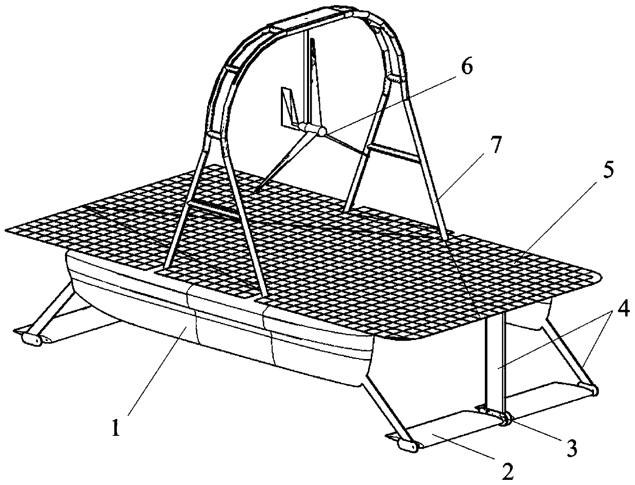
[0024] combine figure 1 , a wing-rudder linkage long-endurance catamaran unmanned boat driven by nature, including catamaran body 1, wave swing hydrofoil 2, wing-rudder linkage mechanism 3, hydrofoil mounting plate 4, solar panel 5, wind power Generator 6 and fan support 7. Relevant electrical equipment such as batteries, control systems, communication systems, etc. are placed inside the chip.

[0025] combine figure 2 , according to the three-dimensional view of the hull, the hull is divided into 3 compartments on the deck, among which the lithium battery compartments near the bow and stern of the hull are the lithium battery compartments, and the larger compartment in the middle is the control compartment for the control system. According to the front view, the deck on the top of the sheet is arched, and the lithium battery compartment and the control cabin ...


PUM


Abstract

The invention relates to a naturally-energy-driven wing-rudder linkage long-endurance twin-hull unmanned boat, and belongs to the field of unmanned boats. The naturally-energy-driven wing-rudder linkage long-endurance twin-hull unmanned boat comprises a twin-hull sheet body, four wave swinging hydrofoils, wing-rudder linkage mechanisms, hydrofoil mounting plates, a solar panel, a wind generator and a fan bracket. Two of the swinging hydrofoils are arranged at the bow and two of the swinging hydrofoils are arranged at the stern, and the swinging hydrofoils are arranged side by side in the widthdirection of a hull. The arrangement method overcomes the structural weight gain burden when the wings are greatly expanded. The front and rear hydrofoils extend towards the bow and the stern correspondingly, so that the hydrofoils utilize the longitudinal motion of the hull in waves and the heave amplitude is larger than the heave amplitude of the bow and the stern of the sheet body, and thus the thrust generated by the hydrofoils is effectively improved. The wing-rudder linkage mechanisms adopt hydraulic transmission devices, the thrust of the hydrofoils on the left side and the right sideof the hull is changed by limiting the rotation range of the swinging hydrofoils on the left side and right side of the hull, a thrust difference is generated to drive the unmanned boat to rapidly rotate the bow, and when the rotation of all the hydrofoils are limited at the same time so that the unmanned boat cannot generate thrust, the unmanned boat can quickly stop, and therefore, the unmannedboat has the capability of rapidly rotating the bow and stopping in an emergency.

Description

technical field [0001] The invention belongs to the field of unmanned boats, and in particular relates to a wing-rudder linkage long-endurance double-hull unmanned boat driven by nature. Background technique [0002] Unmanned boat is a new type of unmanned marine exploration platform, mainly small ships, with high autonomous control and navigation capabilities. It has gradually shown its application prospects and value in the military and civilian fields. It has functions such as ocean detection, environmental monitoring, target detection, and communication relay. Therefore, the development of unmanned boat technology has attracted more and more attention from more and more people. Scholars have invested in the development of unmanned boats. [0003] However, most of the unmanned boats that have been put into use at this stage are diesel-powered high-speed boats. Due to their limited energy, the endurance and self-sustainability of unmanned boats are greatly limited, and it...

Claims


Application Information

Patent Timeline
Patent Type & Authority Applications(China)
IPC IPC(8): B63B35/00B63H21/20B63H1/36B63H25/42
CPCB63H25/50
Inventor 张蔚欣廖煜雷李晔李志晨潘恺文贾琪王博苏玉民
Owner HARBIN ENG UNIV
Learn More