Vehicle and transmission shaft assembly thereof

A transmission shaft and powertrain technology, applied in the field of vehicle transmission system supporting components, can solve the problems of reducing transmission efficiency of transmission shaft, local structure of abnormal noise, high extrusion stress, improve transmission efficiency and vehicle NVH performance, avoid Effects of local overheating, avoidance of noise and structural vibrations

Pending Publication Date: 2019-05-10
ZHEJIANG PANGOOD POWER TECH CO LTD
View PDF13 Cites 0 Cited by
  • Summary
  • Abstract
  • Description
  • Claims
  • Application Information

AI Technical Summary

Problems solved by technology

[0003] The current transmission shaft relies on the spline structure on the shaft to compensate the relative displacement between the powertrain and the drive axle, that is, the transmission is adjusted through the relative sliding between the surfaces of the spline teeth along the axial direction of the transmission shaft. The effective length of the shaft is used to compensate the relative displacement between the powertrain and the drive axle. The extrusion stress on the tooth side of the spline is very high when the torque is transmitted. At this time, the tooth side of the spline relies on relative sliding to adjust the length. Phenomena such as jitter, abnormal noise and local structure overheating not only seriously affect the NVH performance and driving comfort of the whole vehicle, but also reduce the The transmission efficiency of the drive shaft affects the safety and stability of the vehicle

Method used


Image

  • Vehicle and transmission shaft assembly thereof
  • Vehicle and transmission shaft assembly thereof
  • Vehicle and transmission shaft assembly thereof

Examples


Embodiment Construction

[0024] The core of the present invention is to provide a transmission shaft assembly, which has high structural strength and structural rigidity; at the same time, it provides a vehicle using the above transmission shaft assembly.

[0025] In order to enable those skilled in the art to better understand the solution of the present invention, the present invention will be further described in detail below in conjunction with the accompanying drawings and specific embodiments.

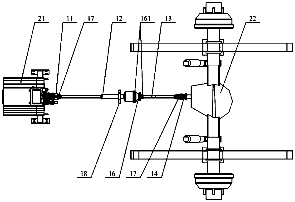
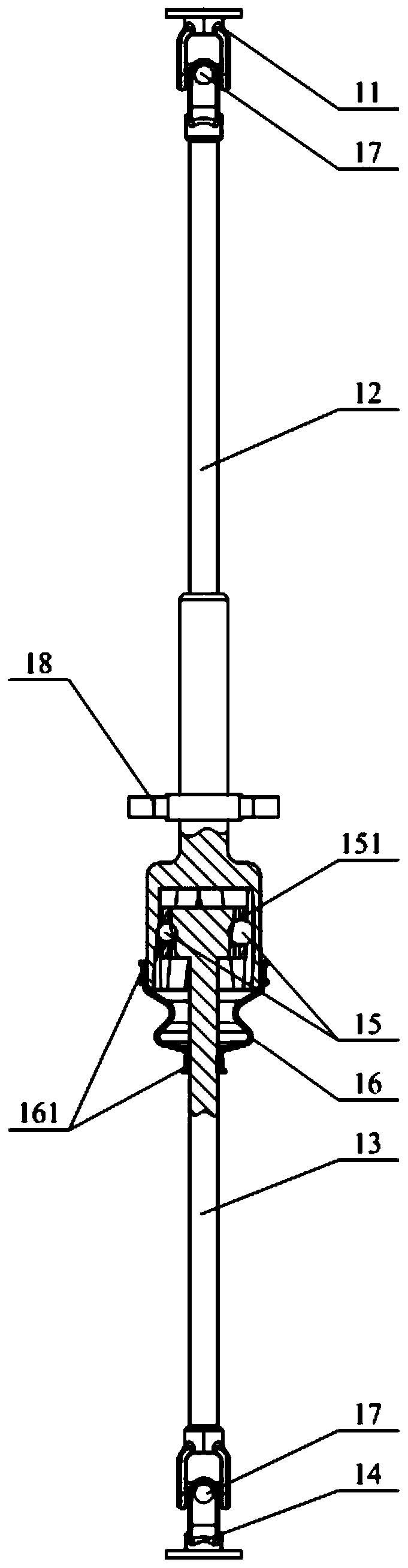
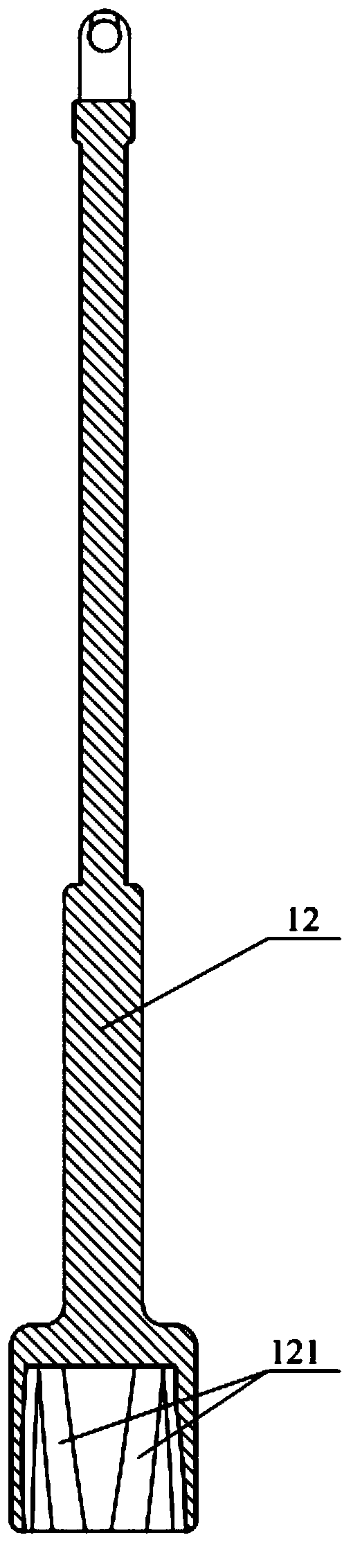
[0026] Please refer to Figure 1 to Figure 4 , figure 1 A schematic diagram of the cooperation structure between the transmission shaft assembly, the power assembly and the drive axle provided by a specific embodiment of the present invention; figure 2 for figure 1 Schematic diagram of the middle transmission shaft assembly; image 3 for figure 2 Enter the structural sectional view of the driven yoke in ; Figure 4 for figure 2 Schematic diagram of the structure of the middle output active fork....


PUM


Abstract

The invention discloses a transmission shaft assembly. The transmission shaft assembly comprises an input active fork and an output passive fork, wherein the input active fork connected with a power assembly, and the output passive fork is connected with a driving axle; an input passive fork and an output active fork are connected between the input active fork and the output passive fork in sequence according to a power transmission direction; the tail end of the input passive fork is mounted outside the head end of the output active fork in a sleeving manner; a plurality of external guide grooves are formed in the internal wall of the tail end of the input passive fork; the external guide grooves are not parallel to the radial section of the input passive fork; a plurality of internal guide grooves corresponding to the external guide grooves in a one-to-one manner and aligned and matched with the external guide grooves in parallel are formed in the external wall of the head end of theoutput active fork; and rolling pieces are movably embedded between the external guide grooves and the corresponding internal guide grooves. The transmission shaft assembly is uneasy to generate shaking, abnormal sounds and local overheating, and the transmission efficiency, the vehicle running stability and comfort can be effectively guaranteed. The invention further discloses a vehicle using the transmission shaft assembly.

Description

technical field [0001] The invention relates to the technical field of supporting components of a vehicle transmission system, in particular to a transmission shaft assembly. The invention also relates to a vehicle using the transmission shaft assembly. Background technique [0002] The transmission shaft is an important transmission component connecting the powertrain and the drive axle. The powertrain is elastically supported on the body or frame through the suspension system, and the powertrain will be displaced and rotated during the operation of the car; the drive axle is connected to the body or frame by the suspension system, and the car runs During the process, the suspension will move, so that the drive axle has a certain position relative to the body or frame. The powertrain and drive axle have displacement relative to the mounting carrier frame or body, which requires the transmission shaft to have telescopic characteristics to compensate for the relative positi...

Claims


Application Information

Patent Timeline
Patent Type & Authority Applications(China)
IPC IPC(8): B60K17/22
Inventor 史玉红毕兰平
Owner ZHEJIANG PANGOOD POWER TECH CO LTD
Why Eureka
Try Eureka