
A method and device for automatic welding of galvanometer laser-hot wire composite pipelines

A composite pipe and automatic welding technology, which is applied in laser welding equipment, welding equipment, metal processing equipment, etc., can solve problems such as weld defects, poor fusion of groove side walls and weld metal, etc.

Active Publication Date: 2021-07-06
HARBIN INST OF TECH AT WEIHAI
View PDF0 Cites 0 Cited by
  • Summary
  • Abstract
  • Description
  • Claims
  • Application Information

AI Technical Summary

Problems solved by technology

[0010] The present invention aims to solve the technical problems of poor fusion between the groove side wall and the weld metal in the narrow gap welding process of ultra-thick materials and the weld seam defects in the non-flat welding process, and provides a high-efficiency and high-stability pipe welding All-position pipeline automatic welding method

Method used


Image

  • A method and device for automatic welding of galvanometer laser-hot wire composite pipelines
  • A method and device for automatic welding of galvanometer laser-hot wire composite pipelines
  • A method and device for automatic welding of galvanometer laser-hot wire composite pipelines

Examples


Embodiment 1

[0039]The 316LN stainless steel pipe with a diameter of 600 mm and a wall thickness of 70 mm is welded by using the galvanometer laser-hot wire TIG composite pipe automatic welding welding technology in this embodiment. The specific experimental method is as follows:

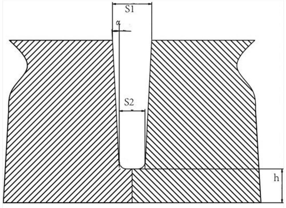
[0040] (1) After the pipes are butted before welding, a combined groove is made. The width S2 of the bottom of the groove is 8mm, the width S1 of the top is 15mm, the angle α of the side wall of the groove is 3°, the thickness h of the blunt edge at the bottom of the groove is 10mm, and the blunt edge The gap is less than 2mm; the shape of the groove and the position of all parameters are as follows image 3 shown;

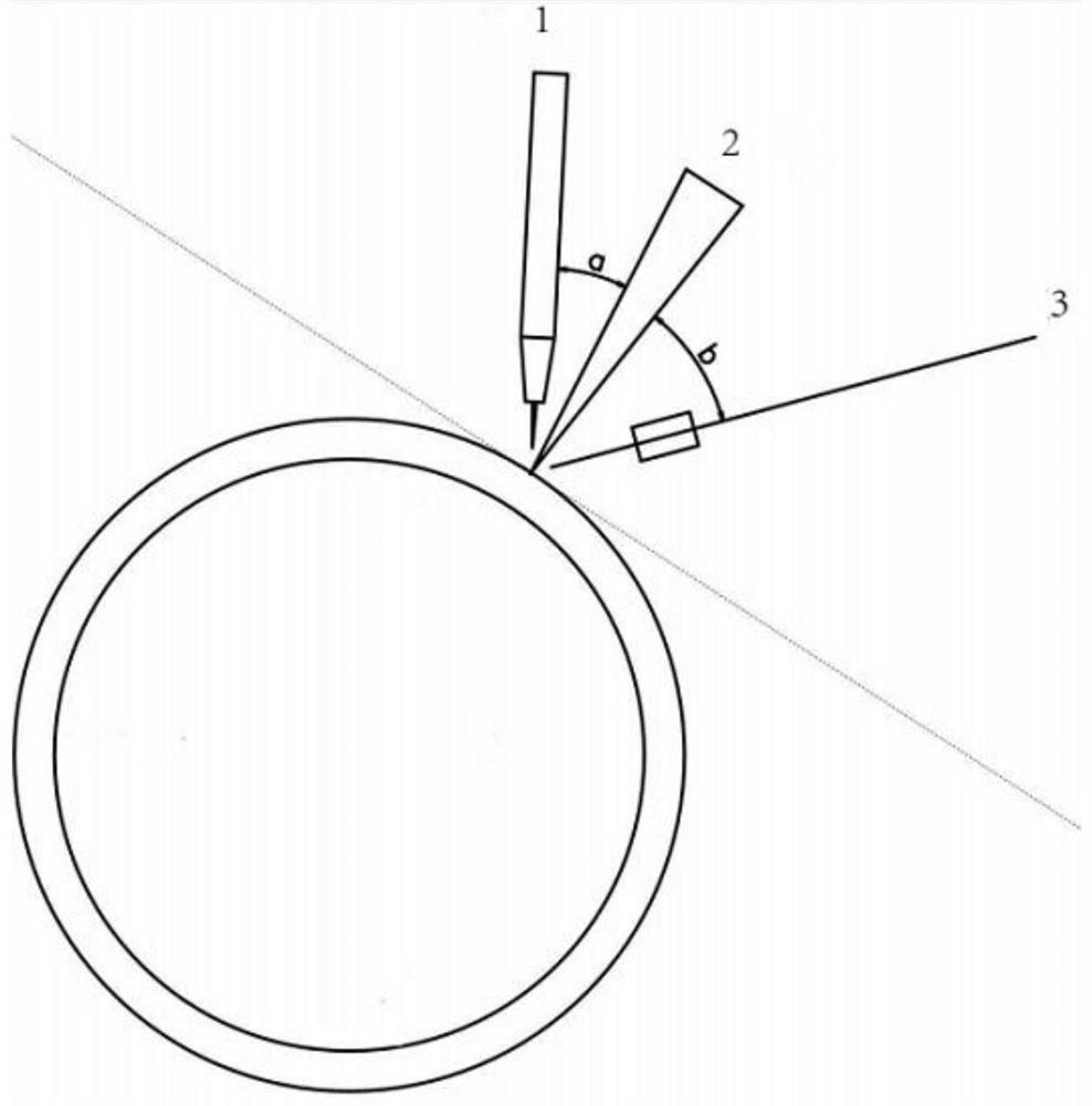
[0041] (2) The welding device is composed of the laser head and the TIG welding torch 1 side shaft and is rigidly connected with the movable trolley. The angle a between the laser beam and the TIG welding torch is adjusted in advance to be 30°, and the laser spot size is 0.6mm. Adjust the laser beam...

Embodiment 2

[0056] The 316L stainless steel pipe with a diameter of 400 mm and a wall thickness of 30 mm is welded by using the galvanometer laser-hot wire TIG composite pipe automatic welding technology in this embodiment. The specific experimental method is as follows:

[0057] (1) After the pipes are butted before welding, a combined groove is made. The width S2 of the bottom of the groove is 8mm, the width S1 of the top is 11mm, the angle α of the side wall of the groove is 3°, the thickness h of the blunt edge at the bottom of the groove is 5mm, and the blunt edge The gap is less than 2mm;

[0058] (2) The welding device is composed of the laser head and the TIG welding torch 1 side shaft and is rigidly connected with the movable trolley. The angle a between the laser beam and the TIG welding torch is adjusted in advance to be 30°, and the laser spot size is 0.5mm. Adjust the laser beam The swing range is -2mm~+2mm, and the protective gas is argon;

[0059] (3) Weld the blunt edge o...


PUM

PropertyMeasurementUnit
widthaaaaaaaaaa
widthaaaaaaaaaa
thicknessaaaaaaaaaa

Abstract

The invention relates to an automatic welding method and device for a galvanometer laser-hot wire composite pipeline, which solves the technical problem of poor fusion between the side wall of the groove and the weld metal in the narrow gap welding process of ultra-thick materials, and specifically includes the following steps: (1) Butt the pipes to open a combination groove, the combination groove is a narrow gap and deep groove, under the condition of shielding gas, adjust the direction and swing amplitude of the laser beam, the angle between the laser beam and the welding torch, and the size of the laser spot; ( 2) Perform galvanometer laser priming welding on the blunt edge of the root of the combined groove; (3) Add welding wire to the combined groove, and under the condition of shielding gas, adjust the swing amplitude of the laser beam, the angle between the welding wire and the laser beam, The distance between the welding wire and the laser spot; (4) The groove is filled and covered by the galvanometer laser-hot wire hybrid welding method. The invention also provides its device. The invention can be widely used in the field of automatic welding of pipelines.

Description

technical field [0001] The invention relates to the field of automatic welding of pipelines, in particular to an all-position automatic welding method for a vibrating mirror laser-hot wire composite pipeline. Background technique [0002] Pipes are widely used in petrochemical, coal, ore, building materials, nuclear power and other important national industrial fields. Excellent welding quality, but also to shorten the welding cycle as much as possible. [0003] At present, the pipe welding method used in actual production in China is mainly arc welding, relying on one welding torch to go around the pipeline for one week or two welding torches to go around the pipeline for half a circle at the same time to complete the bottom welding, and then through automatic welding, semi-automatic welding or manual welding. Carry out the filling and capping of the pipes. With the rapid growth of resource transportation, in order to carry the transfer of a large amount of material resou...

Claims


Application Information

Patent Timeline
Patent Type & Authority Patents(China)
IPC IPC(8): B23K26/348
Inventor 陈波陈志伟檀财旺冯吉才
Owner HARBIN INST OF TECH AT WEIHAI
Learn More