
Film forming device and film forming method

A film forming device and metal film technology, applied in ion implantation plating, metal material coating process, coating, etc., can solve the problems of substrate wrinkles, temperature difference, etc., and achieve the effect of suppressing wrinkles

Inactive Publication Date: 2019-05-07
ULVAC INC
View PDF9 Cites 0 Cited by
  • Summary
  • Abstract
  • Description
  • Claims
  • Application Information

AI Technical Summary

Problems solved by technology

[0003] Here, in the above-mentioned film-forming apparatus, when forming a metal film on a base material composed of a long film or the like, particles of a high-temperature metal material are deposited on the base material, thereby causing a problem under high-temperature deposition. create excessive temperature differences between the object and the substrate, and sometimes create wrinkles in the substrate

Method used


Image

  • Film forming device and film forming method
  • Film forming device and film forming method
  • Film forming device and film forming method

Examples


Embodiment Construction

[0033] Hereinafter, embodiments of the present invention will be described with reference to the drawings.

[0034] (Structure of Film Formation Device)

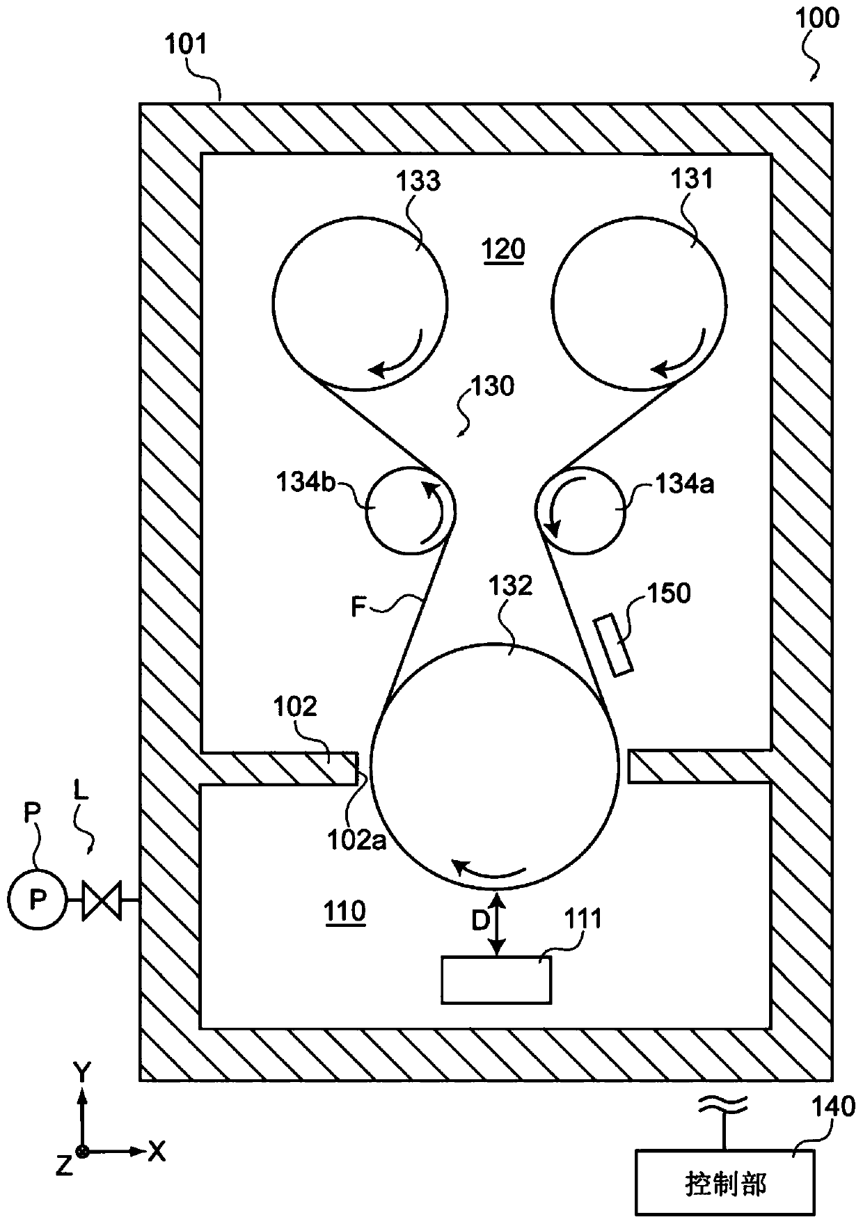
[0035] figure 1 It is a schematic side sectional view showing the structure of the film formation apparatus 100 according to one embodiment of the present invention. figure 1 The illustrated X-axis, Y-axis, and Z-axis directions represent three mutually orthogonal axial directions, the X-axis and Y-axis represent the horizontal direction, and the Z-axis direction represents the vertical direction.

[0036] Such as figure 1 As shown, the film forming apparatus 100 has a vacuum chamber 101 , a film forming unit 110 , a transport unit 120 , a transport mechanism 130 , a control unit 140 , and a preheating unit 150 .

[0037] The vacuum chamber 101 has an airtight structure, and is connected to an exhaust line L having a vacuum pump P. Thus, the vacuum chamber 101 is configured to be able to evacuate the interior to a predet...


PUM


Abstract

A film forming device according to an aspect of the present invention has an unwinding roller, a winding roller, a heating roller, a film forming unit, and a control unit. The unwinding roller unwindsa base material which is a long film. The winding roller winds the base material unwound from the unwinding roller. The heating roller includes a hot bath unit, and is provided between the unwindingroller and the winding roller in the transporting direction of the base material and heats the base material. The film forming unit is provided facing the heating roller, includes an evaporation source having a heating mechanism for heating a metal material, and forms a metal film on the base material. While the base material is being unwound from the heating roller and wound around the winding roller, the control unit controls either the hot bath unit or the heating mechanism so that the temperature difference between the metal film and the base material is greater than 0 DEG C and less than180 DEG C.

Description

technical field [0001] The present invention relates to a film forming device and a film forming method for forming a film of an evaporating material on a substrate (base material) by evaporating the evaporating material. Background technique [0002] Conventionally, film forming apparatuses are known (for example, Patent Documents 1, 2, and 3) in which a base material unrolled from an unrolling roll is wound around a can roll, and a film of an evaporation material is formed on the base material at the same time. , and the substrate is wound up by a take-up roll. [0003] Here, in the above-mentioned film-forming apparatus, when forming a metal film on a base material composed of a long film or the like, particles of a high-temperature metal material are deposited on the base material, thereby causing a problem under high-temperature deposition. excessive temperature difference between the object and the substrate, and sometimes wrinkles on the substrate. [0004] Therefor...

Claims


Application Information

Patent Timeline
IPC IPC(8): C23C14/24C23C14/56
CPCC23C14/24C23C14/56C23C14/541C23C14/562
Inventor 横山礼宽武井应树佐藤昌敏清田淳也
Owner ULVAC INC
Learn More