
LCD defect detection method

A defect detection and defect technology, applied in the field of LCD defect detection, to achieve the effect of simple logic, enhanced contrast, and strong algorithm versatility

Active Publication Date: 2019-05-07
WUHAN JINGLI ELECTRONICS TECH
View PDF6 Cites 14 Cited by
  • Summary
  • Abstract
  • Description
  • Claims
  • Application Information

AI Technical Summary

Problems solved by technology

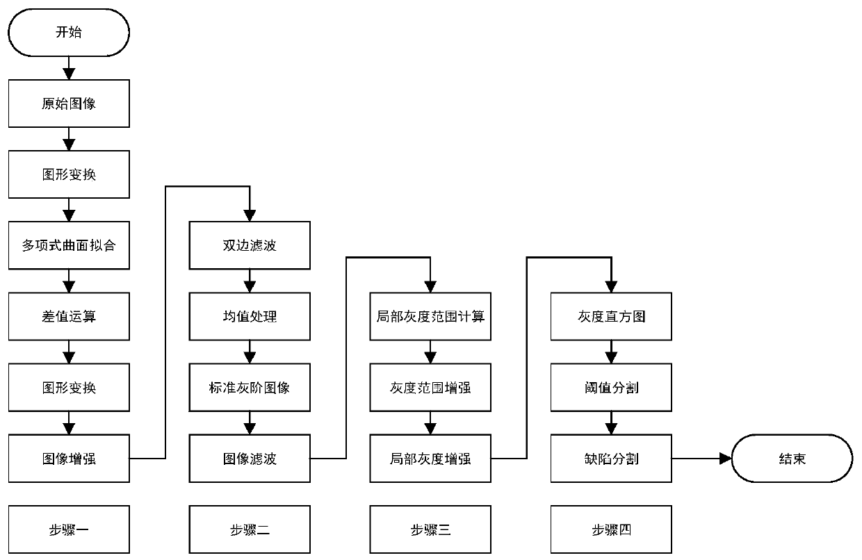
[0005] Aiming at the above defects or improvement needs of the prior art, the present invention provides a method for LCD defect detection, which is performed by fitting the original image, texture filtering, standard mean value conversion, grayscale difference calculation, image enhancement, grayscale histogram After the graph calculation and the segmentation threshold calculation, the defects of the second enhanced image are judged and marked according to the segmentation threshold, so as to detect the defects and defect categories of the original image

Method used


Image

  • LCD defect detection method
  • LCD defect detection method
  • LCD defect detection method

Examples


Embodiment Construction

[0038] In order to make the object, technical solution and advantages of the present invention clearer, the present invention will be further described in detail below in conjunction with the accompanying drawings and embodiments. It should be understood that the specific embodiments described here are only used to explain the present invention, not to limit the present invention.

[0039] In addition, the technical features involved in the various embodiments of the present invention described below can be combined with each other as long as they do not constitute a conflict with each other. The present invention will be further described in detail below in combination with specific embodiments.

[0040] figure 1 It is a schematic diagram of an LCD defect detection method according to an embodiment of the present invention. Such as figure 1 As shown, the specific steps of the method are:

[0041] S1. performing image enhancement on the collected original image to obtain a...


PUM


Abstract

The invention discloses an LCD defect detection method. The method comprises the steps of performing image enhancement on an acquired original image to obtain a first enhanced image; Performing texture filtering and standard mean conversion on the first enhanced image to obtain a standardized gray-scale image; Calculating a gray scale range in the sliding rectangular frame of the standardized grayscale image to obtain a gray scale difference image, and performing image enhancement on the gray scale difference image to obtain a second enhanced image; Calculating a gray histogram of the secondenhanced image, calculating a segmentation threshold value by using the gray histogram, judging defects of the second enhanced image according to the segmentation threshold value, and marking the defects, thereby detecting the defects and defect types of the original image, and realizing synchronization and rapid detection of point, line and mura defects of the LCD panel.

Description

technical field [0001] The invention belongs to the field of module testing, and in particular relates to an LCD defect detection method. Background technique [0002] Liquid crystal display is a flat ultra-thin display device composed of a certain number of color or black and white pixels. It is placed in front of the light source or reflective surface. If an electric field is applied to the liquid crystal, its molecular arrangement will be changed. At this time, if it is equipped with a polarizer , it has the function of preventing light from passing through, that is, light can pass through smoothly when no electric field is applied. If it is combined with a color filter and the voltage applied to the liquid crystal is changed, the amount of light transmitted by a certain color can be changed. It can be said vividly that changing the voltage across the liquid crystal can change its light transmittance. [0003] With the mass production of LCD liquid crystal panels, it is ...

Claims


Application Information

Patent Timeline
IPC IPC(8): G06T7/00G06T7/136G02F1/13
Inventor 马新伍罗巍巍张胜森郑增强
Owner WUHAN JINGLI ELECTRONICS TECH
Learn More