
Substrate discharging mechanical arm and substrate machining system

A manipulator and substrate technology, applied in manipulators, program-controlled manipulators, metal processing equipment, etc., can solve the problems of large space occupation and complicated operation, and achieve the effect of small space occupation, simple operation and stable unloading.

Active Publication Date: 2019-05-07
BEIJING SEMICORE PRECISION MICROELECTRONICS EQUIP CO LTD
View PDF5 Cites 0 Cited by
  • Summary
  • Abstract
  • Description
  • Claims
  • Application Information

AI Technical Summary

Problems solved by technology

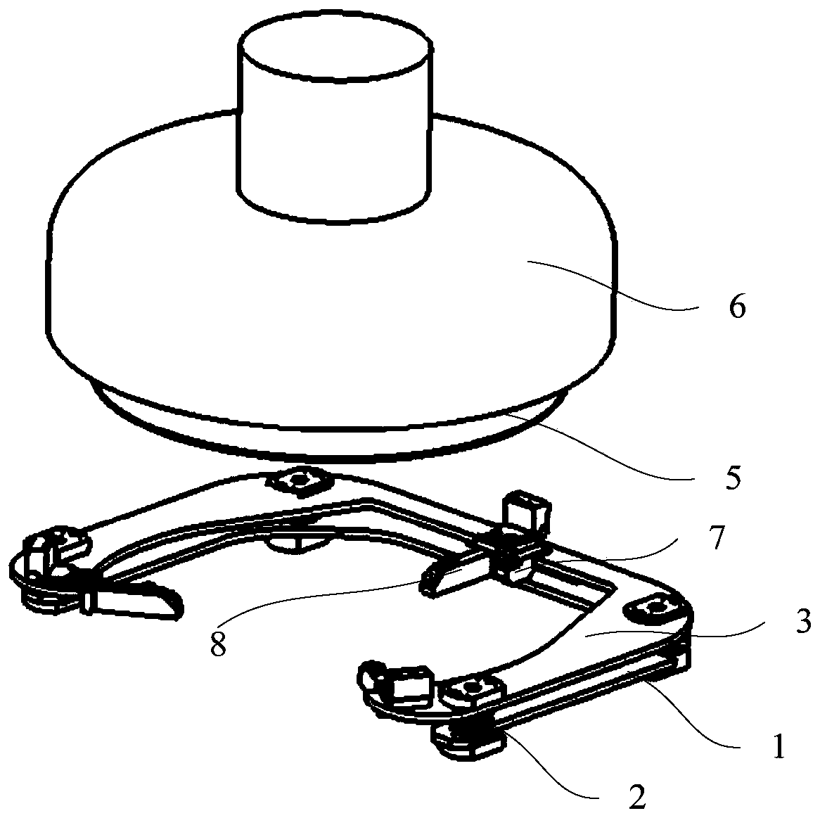
[0004] The purpose of the present application is to provide a substrate unloading manipulator and a substrate processing system including the substrate unloading manipulator, so as to solve the problem in the prior art that the direct unloading of the substrate from the polishing head by the manipulator cannot be realized directly, Technical problems that cause the uninstallation process to be cumbersome and take up a lot of space

Method used


Image

  • Substrate discharging mechanical arm and substrate machining system
  • Substrate discharging mechanical arm and substrate machining system
  • Substrate discharging mechanical arm and substrate machining system

Examples


Embodiment Construction

[0033] The technical solutions of the present invention will be clearly and completely described below in conjunction with the accompanying drawings. Apparently, the described embodiments are some of the embodiments of the present invention, but not all of them.

[0034] The components of the embodiments of the invention generally described and shown in the figures herein may be arranged and designed in a variety of different configurations. Accordingly, the following detailed description of the embodiments of the invention provided in the accompanying drawings is not intended to limit the scope of the claimed invention, but merely represents selected embodiments of the invention.

[0035] Based on the embodiments of the present invention, all other embodiments obtained by persons of ordinary skill in the art without making creative efforts belong to the protection scope of the present invention.

[0036] In the description of the present invention, it should be noted that the...


PUM


Abstract

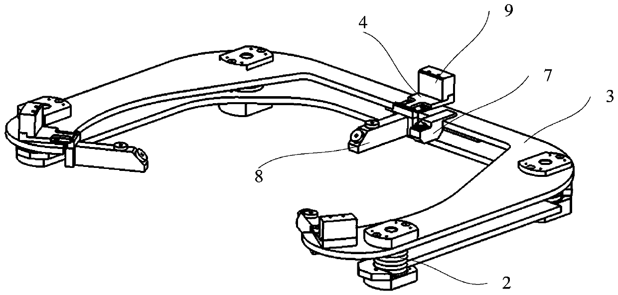
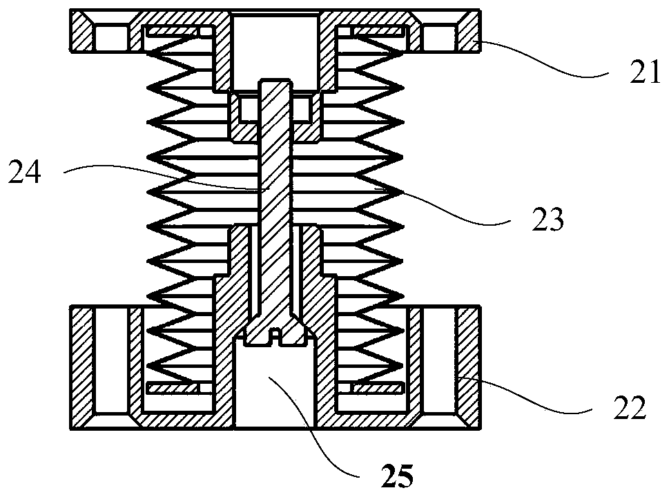
The invention relates to the technical field of IC machining equipment, and particularly relates to a substrate discharging mechanical arm and a substrate machining system. The substrate discharging mechanical arm comprises a pedestal, buffering devices and a floating tray; the pedestal and the floating tray are annular-arm-shaped; the floating tray is located above the pedestal; the buffering devices are located between the floating tray and the pedestal and are used for adjusting a relative position of the floating tray to the pedestal; locating seats are arranged on the floating tray; and polishing head locating oblique planes where a polishing head is located, and substrate locating oblique planes where a discharged substrate is located are arranged on the locating seats. The substratedischarging mechanical arm can be in fit with a driving device to dismount the substrate on the polishing head directly, adjustment on positions of the floating tray can be achieved through the cooperation between the locating seats, the buffering devices and the floating tray in the substrate discharging process, self-adaptive centering between the floating tray and the polishing head can be achieved through swinging of the floating tray, and influence due to an equipment error is corrected, so that stable unloading of the substrate is achieved, the unloading process is easy to operate, andan occupied space is small.

Description

technical field [0001] The invention relates to the technical field of IC processing equipment, in particular to a substrate unloading manipulator and a substrate processing system including the substrate unloading manipulator. Background technique [0002] In the IC processing industry, the substrate needs to undergo polishing, grinding, thinning and other processing processes. Among them, during the operation of the CMP equipment, when the substrate completes the polishing process, the substrate needs to be unloaded from the polishing head first, and then the It is transported to a remote clean area for cleaning, drying and other processes. The unloading process requires a special manipulator structure to ensure that the unloading process is smooth and the position is accurate, so that the substrate can be placed in an accurate position in the cleaning area; and the substrate needs to be moisturized with clean water during transportation to prevent The generation of cryst...

Claims


Application Information

Patent Timeline
Patent Type & Authority Applications(China)
IPC IPC(8): B25J9/00B25J13/08B25J19/00B08B3/02B24B41/00B24B49/00
Inventor 姚远李玉敏费玖海
Owner BEIJING SEMICORE PRECISION MICROELECTRONICS EQUIP CO LTD
Learn More