
Pneumatic vehicle tyre

A technology for pneumatic tires, vehicles, applied in vehicle parts, tire parts, tire tread/tread pattern, etc., to solve block cracks, high pull-out force, cracks at the bottom of the groove and/or block protrusions, etc. question

Inactive Publication Date: 2019-05-03
CONTINENTAL REIFEN DEUTSCHLAND GMBH
View PDF7 Cites 0 Cited by
  • Summary
  • Abstract
  • Description
  • Claims
  • Application Information

AI Technical Summary

Problems solved by technology

These high pull-out forces are problematic, especially in the case of carbon center beam extensions made of a different rubber material than the rest of the tread, so that during demoulding in the area of ​​the carbon center beam the groove bottom and / or or cracks may occur at the block protrusions and cracks may occur at the tread blocks

Method used


Image

  • Pneumatic vehicle tyre
  • Pneumatic vehicle tyre
  • Pneumatic vehicle tyre

Examples


Embodiment Construction

[0017] The pneumatic tire for vehicles embodied according to the invention is in particular a winter tire of the radial type for passenger cars, vans or light trucks. Hereinafter, the present invention is explained by way of example based on a winter tire provided for passenger cars.

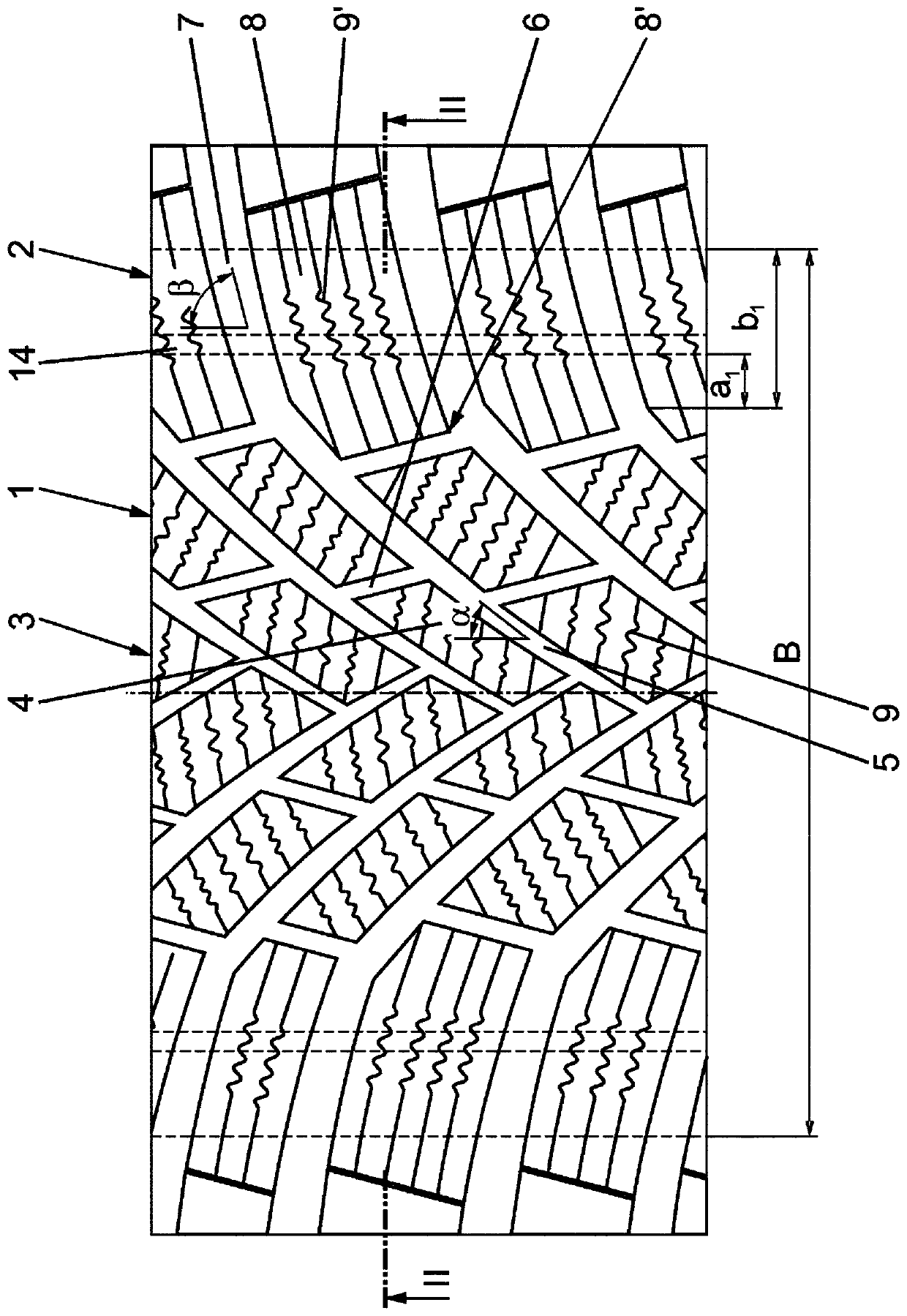
[0018] figure 1 The tread 1 shown is implemented in a directional manner and has a contact patch width B corresponding to the width of the resting footprint determined according to the E.T.R.T.O. The tread 1 has two shoulder-side block rows 2 and between the two shoulder-side block rows a central tread region 3 constructed of a plurality of blocks 4 .

[0019] In the embodiment variant shown, the central tread region 3 is provided with oblique sipe 5 and short sipe 6 extending between adjacent oblique sipe 5 in the circumferential direction, wherein , the oblique grooves 5 and the short grooves 6 together define the blocks 4 . The oblique grooves 5 run at an angle α of 30° to 60°, in particul...


PUM


Abstract

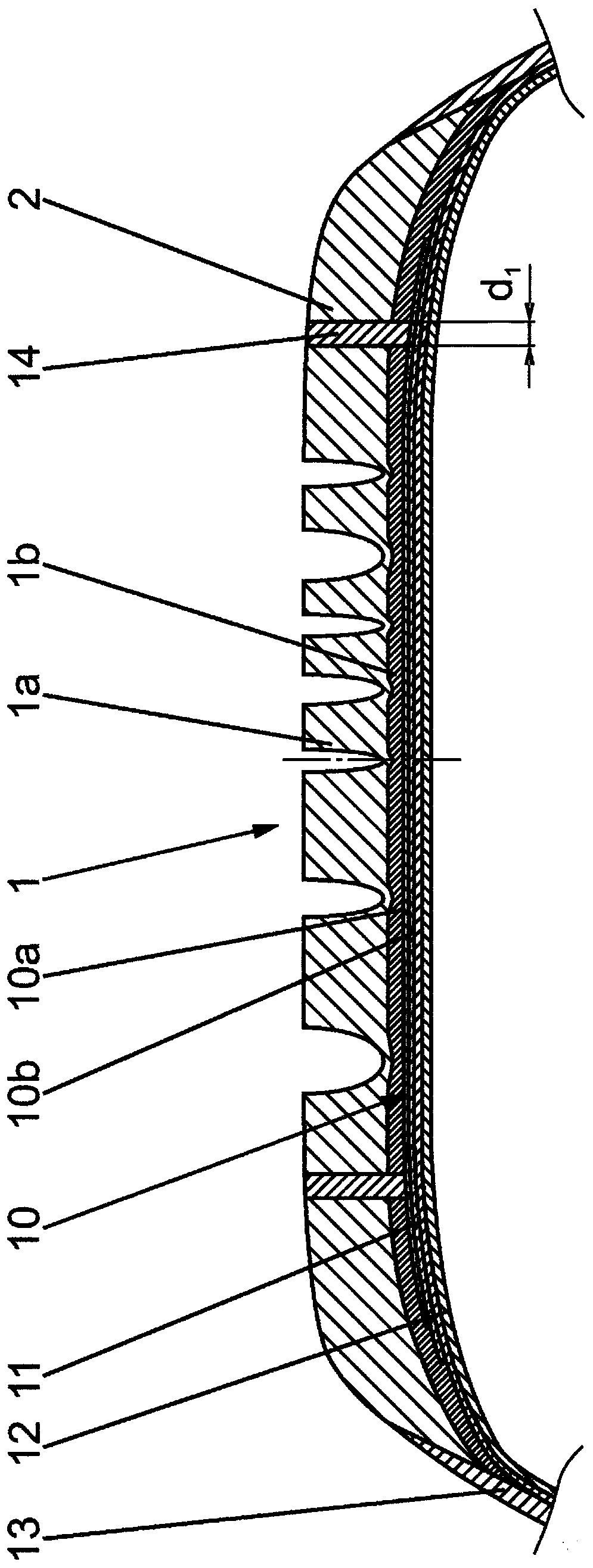
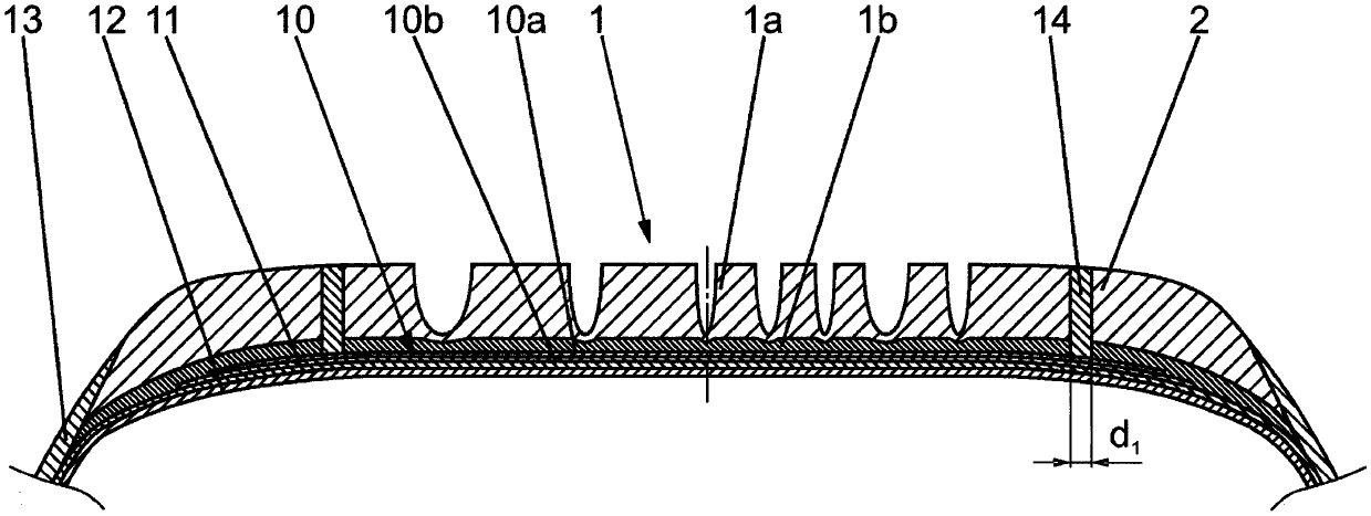
Pneumatic vehicle tyre with a profiled tread (1), which consists of electrically nonconductive rubber material and has a central tread region (3) and on each of the shoulder sides a row of profile blocks (2) with transverse grooves (7), which extend in relation to the circumferential direction at an angle (Beta) of 70 DEG to 90 DEG, wherein the shoulder-side profile blocks (8) have towards the centre of the tread block ends (8'), wherein the central tread region (3) is divided into a multiplicity of profile blocks (4) and is provided with grooves (5), which extend in relation to the circumferential direction at angles (a) of at most 60 DEG, wherein all of the profile blocks (4, 8) are each provided with a number of sipes (9, 9'), and wherein the tread (1) is passed through in the radial direction by at least one circumferentially running electrically conductive rubber strip (14), which forms an electrically conductive passage between the substructure of the tyre and the outer surface of the tread. The tread (1) is passed through in at least one of the shoulder-side rows of profile blocks (2) by an electrically conductive rubber strip (14), which is at a distance (al) of at least 3.0 mm from the nearest block corners (8') of the shoulder-side profile blocks (8) or block-like profile positives.

Description

technical field [0001] The present invention relates to a radial type pneumatic vehicle tire having a patterned tread made of a non-conductive rubber material and having a central tread region, and in each tread The shoulders have rows of blocks or block reliefs with transverse grooves extending at an angle of 70° to 90° relative to the circumferential direction, wherein the shoulder side blocks or the blocks The lugs have a block angle towards the center of the tread, wherein the central tread area is subdivided into blocks and / or block-like lugs and provided with sipe, which are arranged at an angle relative to the circumferential direction an angular extension of at most 60°, wherein all the blocks and / or block reliefs are each provided with a plurality of sipes, and wherein at least one conductive rubber strip extending in the circumferential direction extends in the radial direction Across the tread, the strip of rubber forms an electrically conductive pathway between th...

Claims


Application Information

Patent Timeline
IPC IPC(8): B60C19/08B60C11/03B60C11/12B60C11/00
CPCB60C11/0306B60C11/0302B60C11/0058B60C2011/0358B60C11/005B60C11/12B60C11/0075B60C11/00B60C11/03B60C19/08B60C11/0311B60C2011/1213B60C11/11B60C19/082B60C11/01B60C11/0304B60C11/1204
Inventor 克里斯蒂安·韦伯马蒂亚斯·森克里什纳库马·拉格胡
Owner CONTINENTAL REIFEN DEUTSCHLAND GMBH
Learn More