Leakage protection detection circuit and its control method

A detection circuit and leakage protection technology, applied in emergency protection circuit devices, circuit devices, emergency protection devices with automatic disconnection, etc., can solve the problem that the drive module cannot work normally and light up the LED light bar, and the drive module cannot work normally. , lamp replacement or inconvenient replacement, etc.

Active Publication Date: 2020-10-27
QX MICRO DEVICES
View PDF10 Cites 0 Cited by
  • Summary
  • Abstract
  • Description
  • Claims
  • Application Information

AI Technical Summary

Problems solved by technology

[0007] 1. At the position of the replaced LED light bar, the fluorescent lamp driving electronic ballast used before has been removed, and the input of the test LED light bar is mains power; at this time, there will be a situation that makes the current During the installation process of the LED lighting module, or when other accidents occur, one end of the lighting module has been connected to the live line L of the mains, and the human body accidentally touches the other end of the LED lighting module; When inputting from the live wire to the ground, it can be understood as the series connection of two impedances. The impedance of the LED lamp module is assumed to be RB, and the impedance of the human body is assumed to be RH, such as figure 2 Shown in the middle dotted line box; when the impedance RH of the human body and the impedance RB of the lamp are of the same order of magnitude or close, the current of the mains voltage will pass through the lamp to the human body and then to the earth, and at this time it will be at the impedance RH of the human body A large voltage is formed on the upper, so that the human body is shocked by electric shock, and there is a danger of electric shock;
[0008] 2. In the position of the replaced LED light bar, the fluorescent lamp driving electronic ballast used before has not been removed, then the input of the test LED light bar is the output of the ballast, and the input of the ballast is the mains power; at this time, Since the ballast is still connected to the mains, the output of the ballast is a normal no-load output, that is, a high-voltage and high-frequency AC output of about AC800v80kHz; During the installation process, or when other accidents occur, one end of the lamp module has been connected to the output of one end of the ballast. At this time, the human body accidentally touches the other end of the LED lamp module; One end of the output, through the LED lamp module, the voltage from the human body to the earth is also a high-voltage alternating current, so that the human body is shocked by electric shock, and there will be a danger of electric shock;
[0009] 3. After the mains is input by an isolated power supply, such as a voltage regulator, an isolation transformer, etc., the input of the test LED light bar is isolated from the mains at this time, that is, there is no DC current loop. Therefore, there is no electric shock or shock when the human body is touched at this time. It is dangerous to get an electric shock; but since the isolated power supply needs to use an isolation transformer, its output, that is, the input of the test LED strip light, is equivalent to connecting a large inductor in series; if the power is turned on at this time, due to the existence of the leakage detection module, it will The parasitic input inductance of the isolation transformer is misjudged as human contact, which causes the following driver module to fail to work normally and light up the LED light bar
[0010] The technical characteristics and disadvantages of traditional technology are: image 3 As shown, the traditional leakage protection, when the lighting LED driver module is connected to the mains, can detect whether it is abnormally connected to the mains through chip control; but when there is an electronic ballast, the traditional leakage protection cannot handle it normally , so that the driving module behind it cannot work normally and the LED light bar cannot be lit normally; at the same time, if there is a large inductance in the input of the entire module, the detection module will also misjudge; therefore, professional technical installers are required for this module. Replacement, causing great inconvenience and danger to the replacement or replacement of lamps

Method used


Image

  • Leakage protection detection circuit and its control method
  • Leakage protection detection circuit and its control method
  • Leakage protection detection circuit and its control method

Examples


Embodiment Construction

[0051] The present invention will be described in further detail below in conjunction with accompanying drawing:

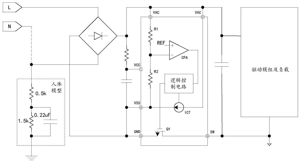
[0052] see Figure 4 to Figure 6 As shown, the present invention provides a novel mains leakage detection circuit, which includes a voltage input terminal, a rectifier circuit, a control module circuit, a drive module and an LED load; The live wire end and the neutral wire end; the input end of the rectification circuit is connected to the output end of the electronic ballast, the output end of the rectification circuit is connected to the input end of the control module circuit, and the control module circuit controls the drive module and the LED load power supply.

[0053] In this embodiment, the rectifier circuit is a rectifier bridge including two AC input terminals, a positive output terminal, and a negative output terminal, and the output terminal of the electronic ballast includes a first output terminal and a second output terminal, so The input terminal...


PUM


Abstract

The invention relates to a leakage protection detection circuit and a control method thereof. The leakage protection detecting circuit comprises a voltage input terminal, a rectifying circuit, a control module circuit, a driving module group and an LED load. The voltage input terminal includes a live wire end and a zero line end that are connected with an input terminal of an electronic ballast. The input terminal of the rectifying circuit is connected with the output terminal of the electronic ballast; and the output terminal of the rectifier circuit is connected to the input terminal of thecontrol module circuit. The control module circuit controls the power supply for the driving module group and the LED load. In addition, the control module includes: absorbing an inputted voltage dividing high-frequency signal of an integrator circuit and filtering an inputted high-frequency alternating-current signal; and carrying out integral detection on the high-frequency filtered signal by achip and inputting different ICCT currents to determine whether the input has a body electric leakage phenomenon. Therefore, an objective of leakage protection detection and control is achieved.

Description

technical field [0001] The invention relates to a leakage protection system, in particular to a leakage protection detection circuit and a control method thereof. Background technique [0002] The development of lighting has changed from ordinary tungsten lamps to fluorescent lamps, and now LED lamps are developing very rapidly. The style of the light bulb has also undergone great changes, especially for fluorescent lamps, the elongated lamp tube is conducive to production, has various advantages such as luminous efficiency, and is widely used in various application environments such as factories, indoors, and buildings. [0003] LED lamps, which are strongly supported by the country, are more and more popular and supported by customers because of their energy saving and environmental protection. Among them, as a series of long lamp tubes to replace, LED lamps as a whole need to be made into long strips similar to fluorescent tubes. shape structure, such as figure 2 shown ...

Claims


Application Information

Patent Timeline
Patent Type & Authority Patents(China)
IPC IPC(8): G01R31/52H02H3/32
Inventor 李剑黄朝刚
Owner QX MICRO DEVICES
Why Eureka
Try Eureka