
Method and system for calculating absolute machining surface shape of reflector

A calculation method and technology of a calculation system, applied in the field of optical detection, can solve problems such as no calculation method, only qualitative evaluation, and inability to build a detection optical path, so as to achieve the effect of convenient and accurate calculation

Active Publication Date: 2019-05-03
CHANGCHUN INST OF OPTICS FINE MECHANICS & PHYSICS CHINESE ACAD OF SCI
View PDF7 Cites 3 Cited by
  • Summary
  • Abstract
  • Description
  • Claims
  • Application Information

AI Technical Summary

Problems solved by technology

In order to ensure the imaging quality of the optical system, it is necessary to obtain the surface shape data of the mirror support in each attitude, but in most cases it is impossible to build such a detection optical path
More often, the designer uses the structural finite element analysis method to calculate the gravitational deformation results of the mirror under different attitudes on the basis of the ideal mirror surface. However, we often find that the calculated surface shape results are much smaller than the surface shape detected by processing. The reason is that we cannot use the absolute processed surface shape as the initial surface shape for calculation and analysis, so the calculation results can only qualitatively evaluate the supporting surface shape of the mirror.
[0005] In summary, it is of great research and application value to extract the absolute processing surface shape of the mirror surface from the optical detection surface shape as the evaluation standard of optical processing and as the initial input surface shape of the mirror support analysis of large-aperture mirrors, but there is no Corresponding mature calculation method

Method used


Image

  • Method and system for calculating absolute machining surface shape of reflector
  • Method and system for calculating absolute machining surface shape of reflector
  • Method and system for calculating absolute machining surface shape of reflector

Examples


Embodiment 1

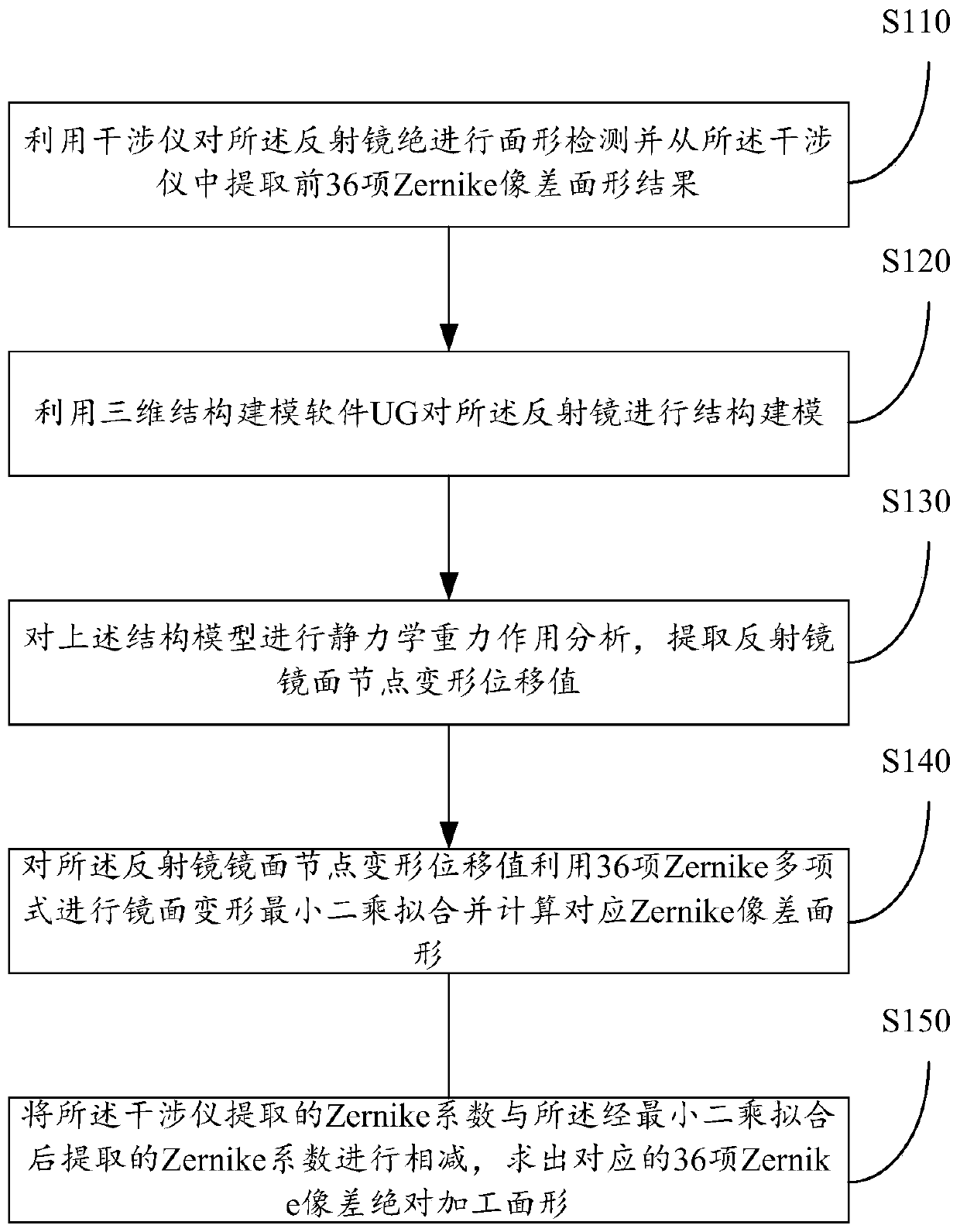
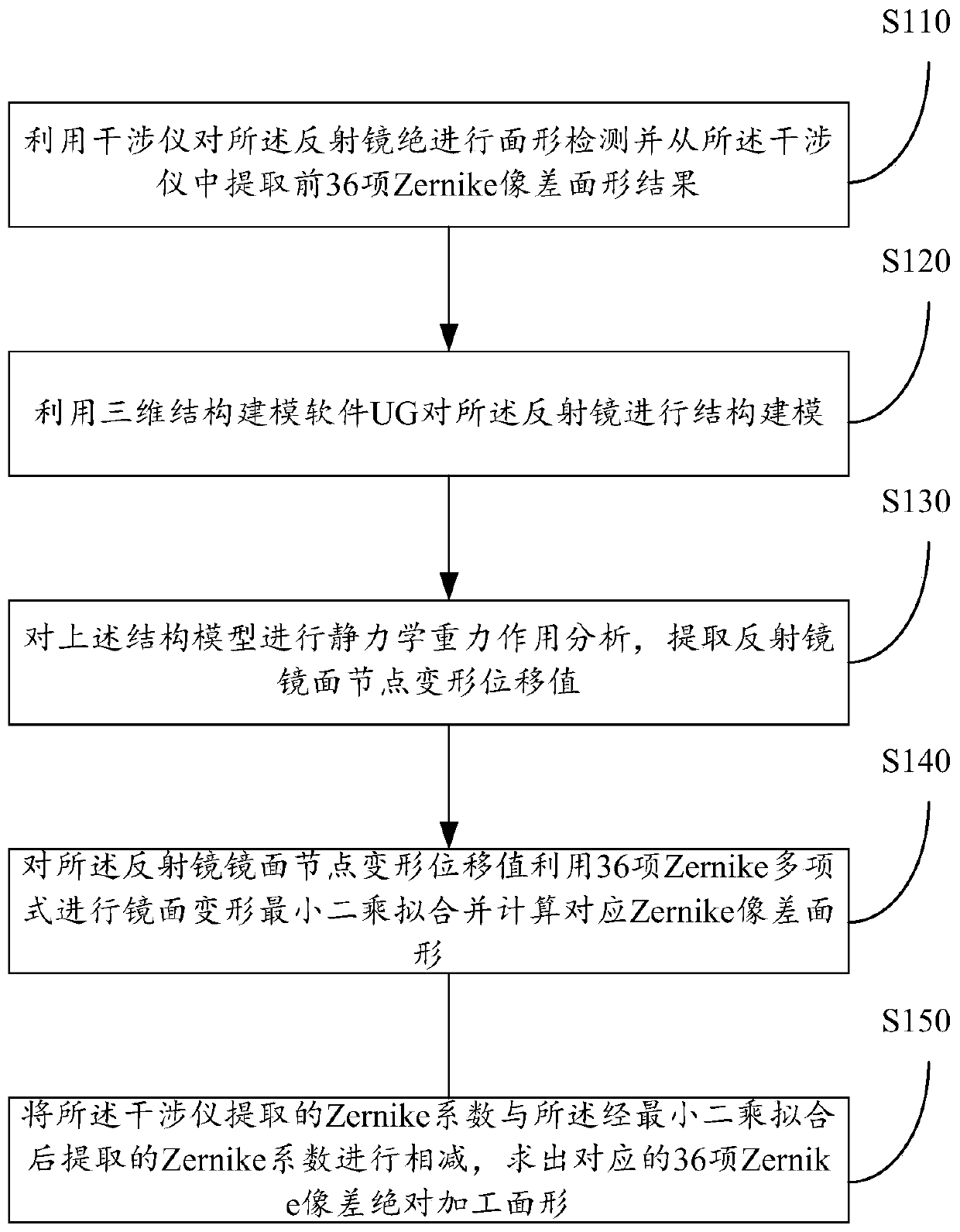
[0032] see figure 1 , the present invention provides a flow chart of the calculation method for the absolute processing surface shape of the mirror, including the following steps:

[0033] Step S110: Use the interferometer to detect the surface shape of the mirror and extract the first 36 Zernike aberration surface shape results from the interferometer, and record it as W opt=a 1 ·Z 1 +a 2 ·Z 2 +a 3 ·Z 3 +…+a 36 ·Z 36 , where W opt is the surface shape detected by the interferometer, Z i is the i-th Zernike polynomial, a i Zernike coefficients extracted for the interferometer.

[0034] It can be understood that the surface shape of the mirror can be expressed by using Zernike aberration. By placing the mirror to be inspected on the inspection tool, an optical inspection optical path is built, and the interferometer is used for surface inspection and the first 36 Zernike items are extracted from the interferometer. Aberration Surface Results.

[0035] In some prefe...

Embodiment 2

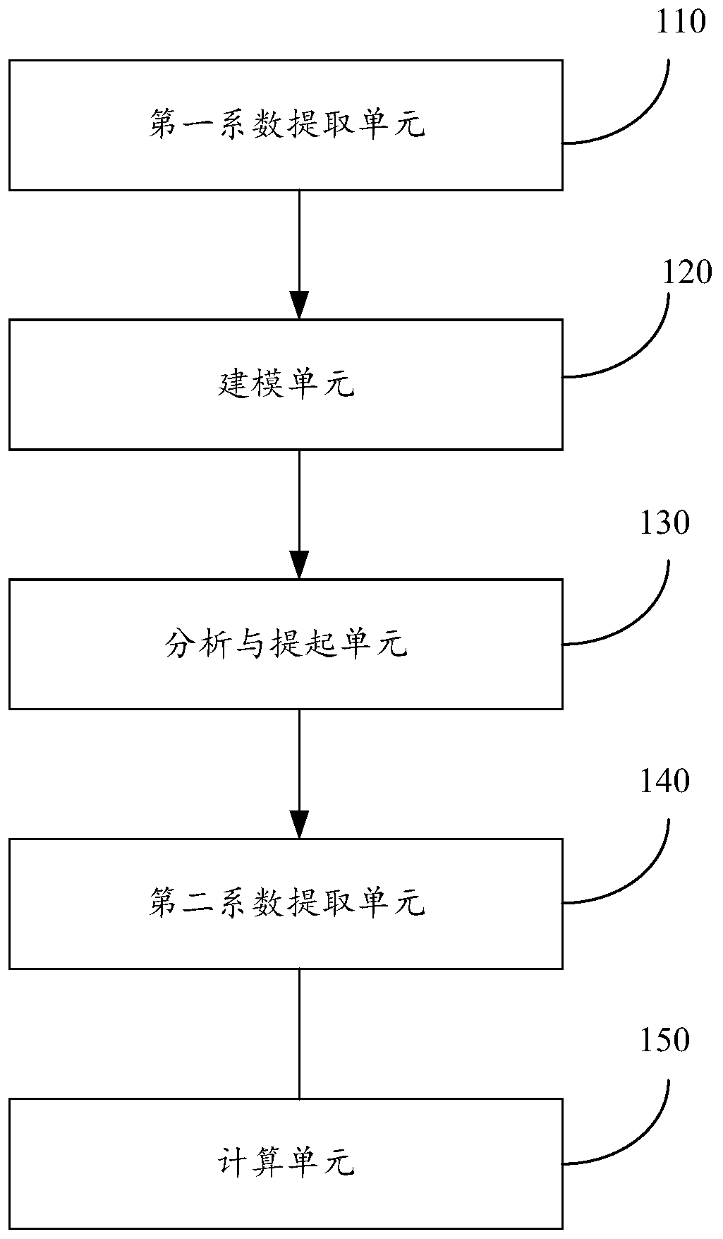
[0045] see figure 2 , the present invention provides a structural schematic diagram of a computing system for the absolute processing surface shape of a mirror, including:

[0046] The first coefficient extraction unit 110: use the interferometer to detect the surface shape of the mirror and extract the first 36 Zernike aberration surface shape results from the interferometer, and denote it as W opt =a 1 ·Z 1 +a 2 ·Z 2 +a 3 ·Z 3 +…+a 36 ·Z 36 , where W opt is the surface shape detected by the interferometer, Z i is the i-th Zernike polynomial, a i Zernike coefficients extracted for the interferometer.

[0047] It can be understood that the surface shape of the mirror can be expressed by using Zernike aberration. By placing the mirror to be inspected on the inspection tool, an optical inspection optical path is built, and the interferometer is used for surface inspection and the first 36 Zernike items are extracted from the interferometer. Aberration Surface Result...


PUM


Abstract

The invention provides a method and system for calculating an absolute machining surface shape of a reflector. Subduction can be performed on a Zernike aberration detection result of an interferometerduring detection and a result which is calculated by a finite element method and fitted with Zernike aberration under the state, so that a mirror absolute machining surface shape can be obtained. Through the provided with the method and system, the separation of surface shape error caused by the support in a mirror detection surface shape result can be realized, so that the mirror machining surface shape and mirror support surface shape can be better evaluated; and in addition, through the adoption of the provided method and system, accurate calculation on a reflector surface shape under complex working conditions can be conveniently achieved through the extracted mirror machining surface shape.

Description

technical field [0001] The invention relates to the technical field of optical detection, in particular to a calculation method and system for the absolute processed surface shape of a mirror. Background technique [0002] The mirror surface shape of an optical mirror is one of the important indicators for optical processing and mirror support. Since the influence of gravity on the surface shape of the mirror cannot be got rid of, the surface shape of the mirror actually detected by us is precisely the superposition of the surface shape of the gravity load and the absolute optical processing surface shape of the mirror under certain constraints of a certain degree of freedom. [0003] Optical processing: Most processors regard the superimposed surface shape detected above as the optical processing surface shape, and ignore the influence of the gravitational load on the mirror surface shape of the mirror under different inspection tools. For small-aperture reflectors, when l...

Claims


Application Information

Patent Timeline
Patent Type & Authority Applications(China)
IPC IPC(8): G01B11/24
Inventor 范磊王建立李洪文王文攀司丽娜
Owner CHANGCHUN INST OF OPTICS FINE MECHANICS & PHYSICS CHINESE ACAD OF SCI
Learn More