Sealing system of radiation chamber furnace tube of tube-type heating furnace

A tubular heating furnace and sealing system technology, which is applied to electric furnace heating, lighting and heating equipment, furnaces, etc., can solve the problems of occupying maintenance space, complicated construction procedures, and difficult to find furnace tube problems, so as to avoid through seams and seal good effect

Inactive Publication Date: 2019-05-03
王振清 +1
View PDF0 Cites 0 Cited by
  • Summary
  • Abstract
  • Description
  • Claims
  • Application Information

AI Technical Summary

Problems solved by technology

[0004] 1. The heated medium flows in the tube, so it is limited to heating gas or liquid
Moreover, these gases or liquids are usually flammable and explosive hydrocarbon media, which are more dangerous than boiler heating water or steam, and the operating conditions are harsh.
[0005] 2. The heating method is direct fire type
[0006] 3. Only burn liquid or gaseous fuel
Although this structure can solve the problem of furnace tube sealing, the sealing effect is good, but the construction procedure is complicated, the structure is huge, and it occupies a certain maintenance space, and it is difficult to find problems with the furnace tube

Method used


Image

  • Sealing system of radiation chamber furnace tube of tube-type heating furnace
  • Sealing system of radiation chamber furnace tube of tube-type heating furnace
  • Sealing system of radiation chamber furnace tube of tube-type heating furnace

Examples


Embodiment 2

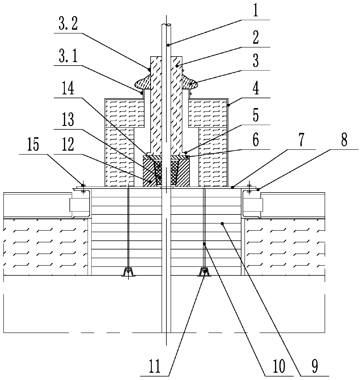
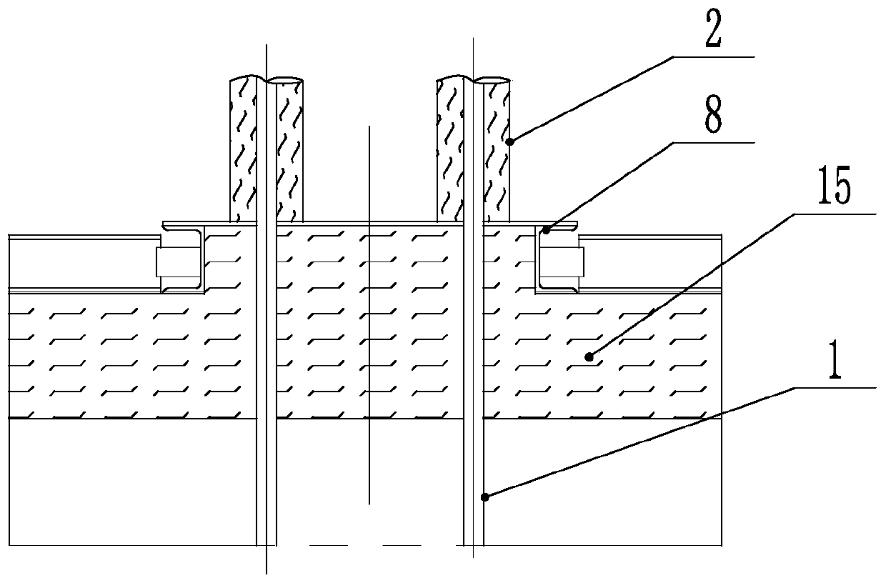
[0098] Such as figure 2 As shown, the furnace tube sealing system of the radiant chamber of the tube heating furnace according to the present invention includes a furnace roof slide plate 7 arranged around the furnace tube 1. The seal arranged on the tube 1, the heat preservation sleeve 2 is arranged around the furnace tube 1 above the seal, the seal and the heat preservation sleeve 2 are provided with a seal box 4, and the heat preservation sleeve 2 protrudes from the seal box 4 to be set; the seal box 4 and There is a margin of activity between the insulation sleeve 2, and a margin of activity between the sealing box 4 and the sealing member;

[0099] The seal includes a seal base 12, the bottom of the seal base 12 is slidably connected to the top slide plate 7, and the seal base 12 runs through the seal base 12 longitudinally to provide a tapered hole, and the tapered hole is provided with a tapered seal. The conical seal is set in cooperation with the conical hole, the u...


PUM


Abstract

The invention relates to a sealing system of a radiation chamber furnace tube of a tube-type heating furnace, and belongs to the technical field of tube-type heating furnace sealing. The sealing system comprises a furnace top sliding plate arranged around the furnace tube, wherein the furnace top sliding plate is used for slip connection with a furnace top; a sealing element surrounding the furnace tube is arranged on the furnace top sliding plate; a heat preservation sleeve is arranged above the sealing element around the furnace tube; a sealing box is arranged outside the sealing element andthe heat preservation sleeve; the heat preservation sleeve extends out from the sealing box; the sealing element comprises a sealing base; the bottom of the sealing base is connected to the furnace top sliding plate; a taper hole is formed in the sealing base in a longitudinal direction and penetrates the sealing base; a taper sealing element is arranged in the taper hole and is matched with thetaper hole; the upper end of the taper hole has a big opening; the taper sealing element is set as split type taper sealing elements arranged around the furnace tube; the split type sealing elements are not fixedly connected to each other; a pressure plate is arranged above the sealing base; and the heat preservation sleeve is arranged above the pressure plate. The radiation chamber furnace tube sealing system has a simple structure and a good sealing effect.

Description

technical field [0001] The invention relates to a furnace tube sealing system for a radiation chamber of a tubular heating furnace, belonging to the technical field of sealing of the tubular heating furnace. Background technique [0002] Industrial furnaces are high-temperature reaction equipment and high-temperature heating equipment in the production process. A combustion chamber surrounded by a refractory material that heats a substance, solid or fluid, using the heat generated by the combustion of fuel. There are various furnaces in industry, such as metallurgical furnaces, heat treatment furnaces, kilns, incinerators and steam boilers. [0003] Tube heating furnace is a type of industrial furnace. It is a process heating furnace used in petroleum refining, petrochemical, chemical and chemical fiber industries. It has characteristics that other industrial furnaces do not have: [0004] 1. The heated medium flows in the tube, so it is limited to heating gas or liquid. ...

Claims


Application Information

Patent Timeline
Patent Type & Authority Applications(China)
IPC IPC(8): F27B17/00F27D11/00
Inventor 王振清周洁宇
Owner 王振清
Why Eureka
Try Eureka