Self-adaptive counterweight structure of beam-pumping unit
A beam pumping unit, self-adaptive technology, applied in the direction of liquid variable capacity machinery, mechanical equipment, machine/engine, etc., can solve the problems of cumbersome application and low efficiency, and achieve reduced damage, convenient installation, and simple appearance Effect
- Summary
- Abstract
- Description
- Claims
- Application Information
AI Technical Summary
Problems solved by technology
Method used
Image

Examples
Embodiment 1
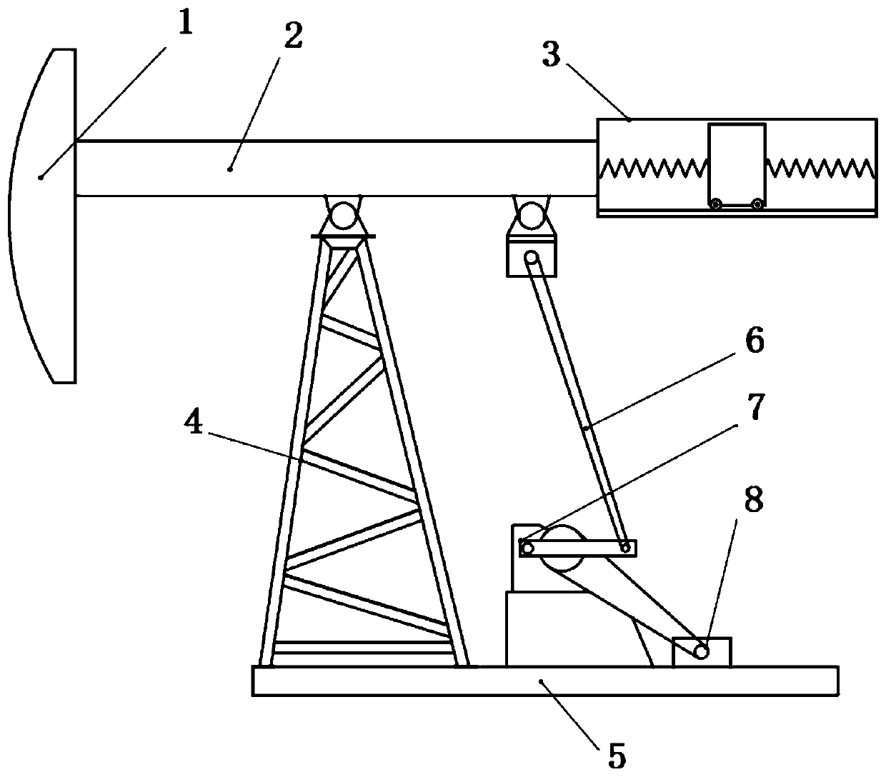
[0028] Such as figure 1 This embodiment is a new type of beam pumping unit. An adaptive counterweight structure is arranged at one end of the pumping unit. one end. The middle part of the beam 2 is arranged on the bracket 4, the bottom of the bracket 4 is fixed on the base 5, and a motor 8 is also arranged on the base 5, and the motor 8 drives the speed reducer 7 to move, and then drives the connecting rod 6 to move, and the connecting rod 6 The other end is connected to the end of the beam 2 close to the self-adaptive counterweight structure 3, thereby driving the beam 2 to move on the bracket 4. The above-mentioned self-adaptive counterweight structure plays the role of being able to adjust the size of the force arm by changing the position, thereby helping to increase the pulling force of the pumping unit and reducing the impact caused by the descent.
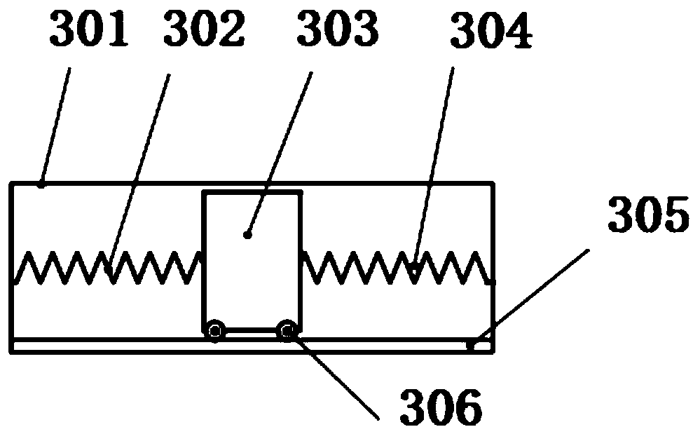
[0029] Such as figure 2 As shown, the self-adaptive counterweight structure includes a box body 301, a counterweight 3...
Embodiment 2
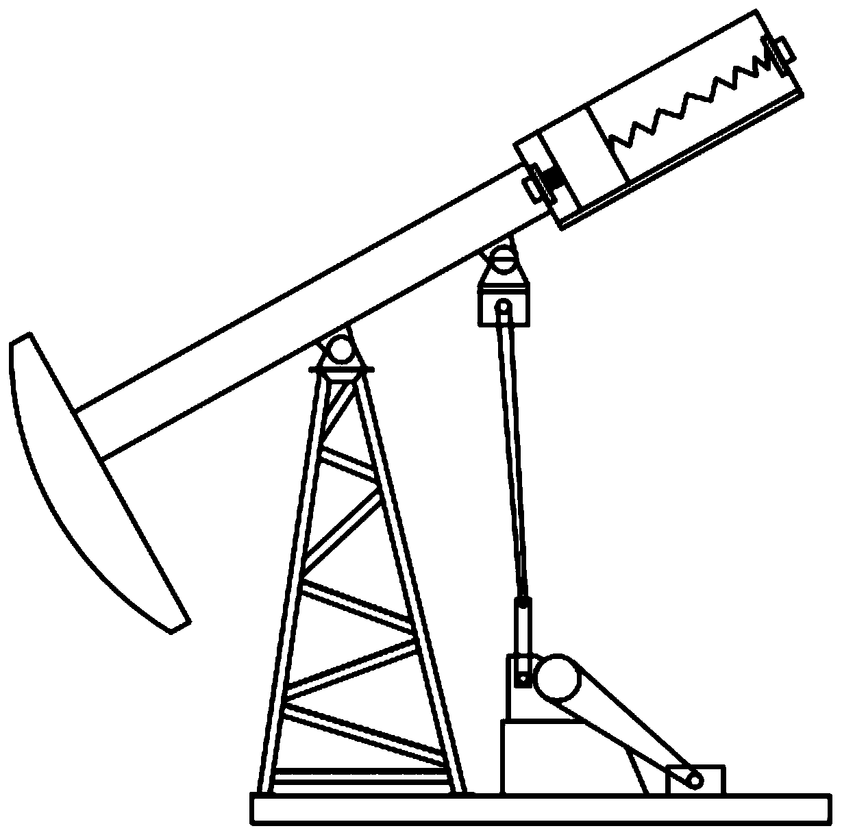
[0038] This embodiment is also an adaptive counterweight structure of a beam pumping unit, and the self-adapting counterweight structure is arranged on the end of the beam of the pumping unit away from the donkey head. Such as Figure 5 As shown, the self-adaptive counterweight structure includes a box body 301, a counterweight 303, a left spring 302, a right spring 304 and a track 305, and the box 301 is provided with a counterweight 303, a left spring 302, a right Spring 304 and track 305, described counterweight 303 is movably placed on track 305, and this track 305 is laid on the top and the bottom in described casing 301 respectively, one end of described left spring 302 and right spring 304 One end of the spring 304 is fixed on both sides of the counterweight 303 oppositely, the other end of the left spring 302 is fixed on the end face of the inner side of the box body 301, and the other end of the right spring 304 is fixed on the end face of the opposite side in the box...
Embodiment 3
[0042] This embodiment is also an adaptive counterweight structure of a beam pumping unit. The self-adaptive counterweight structure is arranged on the end of the beam of the pumping unit away from the donkey head. The self-adaptive counterweight structure includes a box body, Counterweight, left spring, right spring and track, are provided with counterweight, left spring, right spring and track in described casing, described counterweight is movably placed on track, and this track is laid on In the bottom of the box, one end of the left spring and one end of the right spring are respectively fixed on both sides of the counterweight relatively, the other end of the left spring is fixed on the end surface of one side in the box, and the other end of the right spring Fixed on the end face on the opposite side of the box. The counterweight placed on the track moves left and right under the action of gravity to increase or decrease the size of the force arm when the beam swings up...
PUM
 Abstract
Description
Claims
Application Information
 - R&D
- Intellectual Property
- Life Sciences
- Materials
- Tech Scout
- Unparalleled Data Quality
- Higher Quality Content
- 60% Fewer Hallucinations
Browse by: Latest US Patents, China's latest patents, Technical Efficacy Thesaurus, Application Domain, Technology Topic, Popular Technical Reports.
© 2025 PatSnap. All rights reserved.Legal|Privacy policy|Modern Slavery Act Transparency Statement|Sitemap|About US| Contact US: help@patsnap.com