Automatic injection pipe production device

A technology of automatic production and grouting pipe, applied in the field of automatic production of grouting pipe and automatic production equipment of grouting pipe, to achieve the effect of strong adaptability, improving the efficiency and quality of hot-melting, and saving labor costs

Inactive Publication Date: 2019-05-03
山东新雪矿井降温科技有限公司
View PDF3 Cites 1 Cited by
  • Summary
  • Abstract
  • Description
  • Claims
  • Application Information

AI Technical Summary

Problems solved by technology

[0002] At present, there are few equipments for the mechanized production of grouting pipes. Most manufacturers use manual feeding and thermal expansion hose method for production, and there are very few equipments for automatic production of grouting pipes.

Method used


Image

  • Automatic injection pipe production device
  • Automatic injection pipe production device
  • Automatic injection pipe production device

Examples


Embodiment Construction

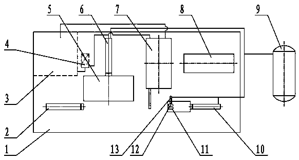
[0022] The technical solution of the present invention will be described in detail below in conjunction with the accompanying drawings.

[0023] combine figure 1 with figure 2 , it can be seen that the automatic production equipment for grouting pipes of the present invention includes a workbench 1, and also includes a high-frequency fuser 7, a material feeding device, a pneumatic linkage device, a computer numerical control device, a cooling circulation pump 4 and a water tank 3, and an air pump 9.

[0024] The blanking and feeding device is composed of a blanking slide 5, a pneumatic push rod I6, and a pneumatic push rod II2; wherein, the blanking slide 5 cooperates longitudinally with the pneumatic push rod I6, and the blanking slide 5 cooperates horizontally with the pneumatic push rod II2.

[0025] The pneumatic linkage device is composed of clamp I11, clamp II12, pneumatic push rod III13, and pneumatic push rod IV10; among them, clamp I11 and clamp II12 cooperate; pne...


PUM


Abstract

The invention belongs to the technical field of an injection pipe production device, and particularly relates to an automatic injection pipe production device. The device can achieve automatic injection pipe production through automatic feeding, and hot melting abut joint. The device comprises a worktable, and further comprises a high-frequency hot melt machine, a discharging feeding device, a pneumatic linkage device, a computer numerical control device, a cooling circular pump, a water tank and an air pump. The aim that according to the injection pipe production device, through automatic feeding and hot melting abut joint, injection pipe automatic production is achieved can be achieved.

Description

technical field [0001] The invention belongs to the technical field of grouting pipe production equipment, in particular to automatic production equipment for grouting pipes, and in particular realizes automatic production of grouting pipes through automatic feeding and hot-melt butt jointing. Background technique [0002] At present, there are few equipments for the mechanized production of grouting pipes. Most manufacturers use manual feeding and thermal expansion hose method for production, and there are very few equipments for automatic production of grouting pipes. Contents of the invention [0003] The invention provides an automatic production equipment for grouting pipes aiming at the shortcomings of less equipment for mechanized production of grouting pipes. [0004] The realization scheme of the patent object of the present invention is: [0005] An automatic production equipment for grouting pipes, including a workbench, characterized in that it also includes a...

Claims


Application Information

Patent Timeline
Patent Type & Authority Applications(China)
IPC IPC(8): B29C65/44B29C65/04
Inventor 王维张建史秀清韩清斌高强郑全盛高慎彪
Owner 山东新雪矿井降温科技有限公司
Why Eureka
Try Eureka