A Stator Core Lamination Welding Die

A stator core and welding mold technology, applied in welding equipment, welding equipment, auxiliary welding equipment, etc., can solve the problems of non-expansion molds that cannot meet the roundness requirements, easy to pull molds, and roundness that cannot meet the requirements. Achieve the effect of ensuring the roundness of the inner circle, ensuring the supporting force, and reducing the deformation of the roundness

Active Publication Date: 2021-02-26
湖南中车商用车动力科技有限公司
View PDF5 Cites 0 Cited by
  • Summary
  • Abstract
  • Description
  • Claims
  • Application Information

AI Technical Summary

Problems solved by technology

The non-inflatable mold with integral mold core cannot meet the roundness requirements, and the mold ejection process is easy to strain the mold; the traditional bulge mold is in the form of full cylindrical surface contact, and anti-deformation is also applied to the part of the stator that does not undergo welding deformation , while offsetting the welding deformation, it causes deformation to other parts, and excessive anti-deformation will also make the roundness not meet the requirements

Method used


Image

  • A Stator Core Lamination Welding Die
  • A Stator Core Lamination Welding Die
  • A Stator Core Lamination Welding Die

Examples


Embodiment Construction

[0024] The present invention will be described in further detail below in conjunction with the accompanying drawings and specific embodiments.

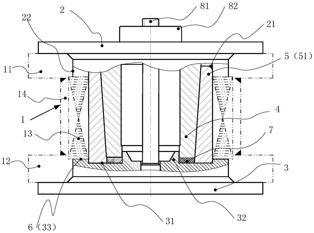
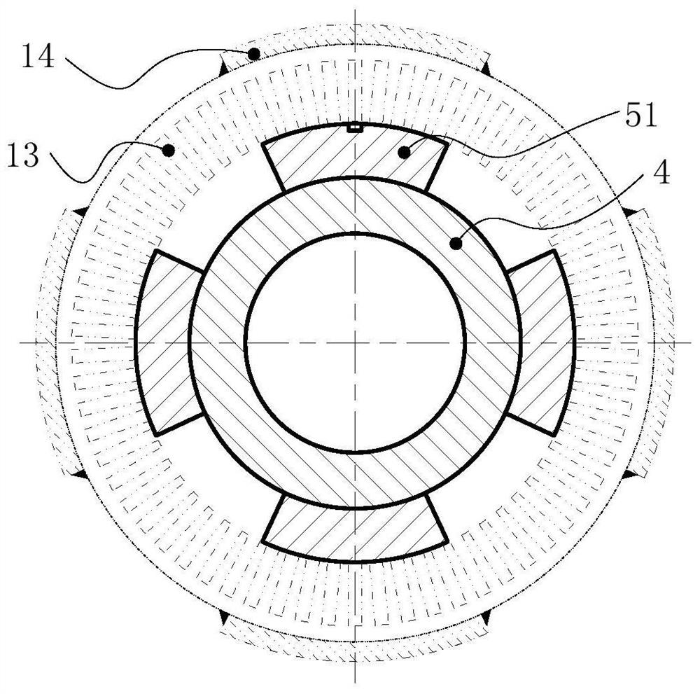
[0025] Such as Figure 1 to Figure 3 As shown, in the stator core lamination welding mold of this embodiment, the stator core 1 includes a stator pull-up ring 11, a stator pull-down ring 12, a stator punch 13 and a plurality of stator pull plates 14, and the stator punch 13 is arranged on the stator pull-up ring 11. Between the ring 11 and the stator pull-down ring 12, a plurality of stator pull plates 14 are evenly distributed on the outer periphery of the stator punching sheet 13, and the welding mold includes an upper pressing plate 2, a lower pressing plate 3, an inner tire 4 and an outer tire 5, and the inner tire 4 and the outer tire 5 are arranged on Between the upper pressing plate 2 and the lower pressing plate 3, the tire 5 includes a plurality of sector blocks 51, the number of sector blocks 51 is equal to the number of sta...


PUM


Abstract

The invention discloses a stator core lamination welding mold. The stator core includes a stator upper ring, a stator lower ring, a stator punch and a plurality of stator pull plates, and the stator punch is arranged between the stator upper ring and the stator lower ring. , a plurality of stator pull plates are evenly distributed on the outer periphery of the stator punching sheet, the welding mold includes an upper pressing plate, a lower pressing plate, an inner tube and an outer tire, the inner tube and the outer tire are arranged between the upper pressing plate and the lower pressing plate, and the outer tire includes a plurality of fan-shaped blocks, the fan-shaped blocks The number is equal to the number of stator pull plates, the inner surface and outer surface of the sector block are arc-shaped, multiple sector blocks are evenly arranged along the outer circumference of the inner tube, and the outer circumference of the plurality of sector blocks is provided with limit pieces, the outer surface of the inner tube is The tapered surface of the inner tube, the inner surface of the sector block is the tapered surface of the outer tire matched with the tapered surface of the inner tube, and the outer surface of the sector block is matched with the inner surface of the stator punch. The invention only applies anti-deformation to the welding deformation position of the stator pull plate, thereby effectively offsetting the welding deformation and ensuring the inner roundness of the stator iron core.

Description

technical field [0001] The invention relates to a stator core welding process in motor equipment, in particular to a stator core lamination welding mold. Background technique [0002] The motor stator core lamination (welding) mold is a mold used for the lamination of the motor stator punching sheets. After the lamination of the punching sheets, it needs to be welded to make the stator a whole. For the organic shell stator, the laminated stator only needs to weld a few buckles symmetrically on the outer circle, and the influence of welding deformation is small. For the caseless stator, several pull plates (usually 4) need to be welded on the outer circle, and the pull rings at both ends, the stator punching piece and the pull plate are welded into a whole to form the stator core, but the welding deformation has a great influence. After lamination of the stator core without casing, four pull plates are welded roughly evenly on the outer circle, so that the stator forms a who...

Claims


Application Information

Patent Timeline
Patent Type & Authority Patents(China)
IPC IPC(8): H02K15/02B23K37/04B23K31/00
Inventor 罗祥程黄德聪尹琨包华羽谭林龙恒陈江秀冯迎怀元炯
Owner 湖南中车商用车动力科技有限公司
Why Eureka
Try Eureka