
Ultrasonic control circuit triggered by position and pressure and welding method

A control circuit and ultrasonic technology, applied in welding equipment, non-electric welding equipment, manufacturing tools, etc., can solve problems such as welding failure and difficulty in starting the vibration of the ultrasonic generator, so as to ensure consistency, facilitate tracking and feedback control, and reduce welding The effect of bad rate

Pending Publication Date: 2019-05-03
东莞市鸿振超声波设备有限公司
View PDF11 Cites 3 Cited by
  • Summary
  • Abstract
  • Description
  • Claims
  • Application Information

AI Technical Summary

Problems solved by technology

In this case, it will be very difficult for the ultrasonic generator to vibrate. For the safety of its own power amplifier, the generator will provide overload protection and turn off the ultrasonic wave, resulting in direct failure of welding.

Method used


Image

  • Ultrasonic control circuit triggered by position and pressure and welding method
  • Ultrasonic control circuit triggered by position and pressure and welding method
  • Ultrasonic control circuit triggered by position and pressure and welding method

Examples


Embodiment Construction

[0040] The principles and features of the present invention are described below in conjunction with the accompanying drawings, and the examples given are only used to explain the present invention, and are not intended to limit the scope of the present invention.

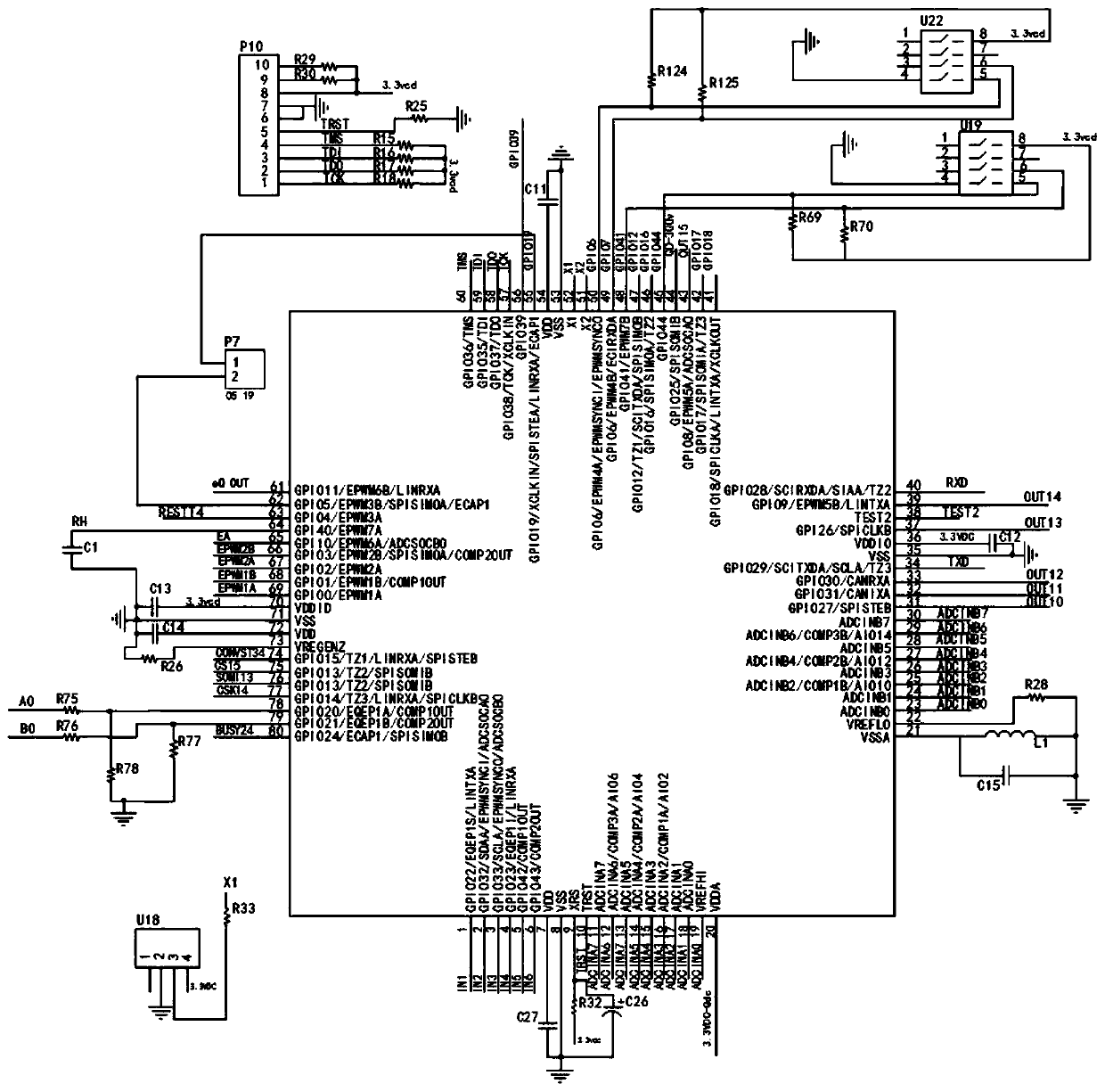
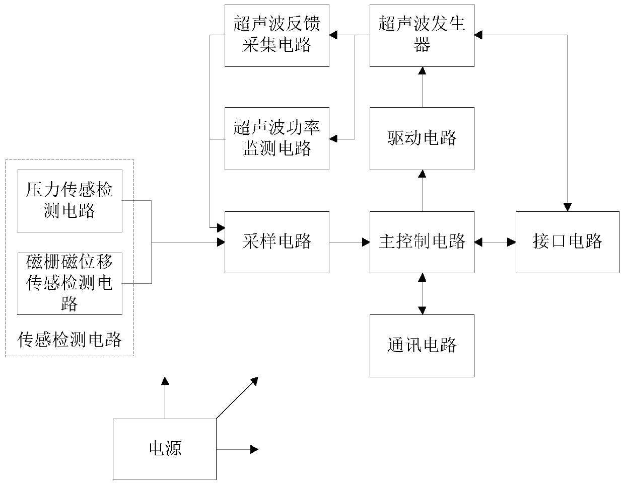
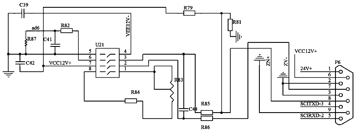
[0041] like figure 1 As shown, an ultrasonic control circuit triggered by position and pressure includes a sensing detection circuit, a sampling circuit, a main control circuit, an interface circuit, a driving circuit and a power supply, the sensing detection circuit is electrically connected to the sampling circuit, The sampling circuit, the interface circuit and the driving circuit are respectively electrically connected to the main control circuit, the driving circuit and the interface circuit are respectively electrically connected to the ultrasonic generator, and the power supply is respectively connected to the sensing detection circuit, the sampling circuit, the The main control circuit, the interface circuit...


PUM


Abstract

The invention relates to an ultrasonic control circuit triggered by position and pressure and a welding method. The ultrasonic control circuit includes a sensing detection circuit body, a sampling circuit body, a main control circuit body, an interface circuit body, a driving circuit body and a power supply, wherein the sensing detection circuit body is electrically connected with the sampling circuit body; the sampling circuit body, the interface circuit body and the driving circuit body are respectively electrically connected with the main control circuit body; and the driving circuit body is electrically connected with an ultrasonic generator. According to the ultrasonic control circuit, the displacement signal of the vibration group of the ultrasonic generator and the pressure signal between an ultrasonic welding head and a product to be welded are collected; the vibration is controlled to a preset amplitude before the ultrasonic welding head is in contact with the product to be welded; time is kept after the ultrasonic welding head is in contact with the product to be welded; the problem that in the welding process, the time occupied by the vibration of the ultrasonic weldinghead to a preset amplitude results in insufficient welding time or the waste of welding energy is avoided; the welding time or the welding energy is accurately controlled; the welding defect rate is greatly reduced; and the consistency of welding products is ensured.

Description

technical field [0001] The invention relates to the technical field of ultrasonic control, in particular to an ultrasonic control circuit and welding method triggered by position and pressure. Background technique [0002] At present, the domestic ultrasonic control system generally uses the time mode or energy mode to control the ultrasonic output to work on the products that need to be welded. Because the products that need to be welded generally have tolerances, plus the fluctuation of the operating voltage of the equipment (the normal fluctuation of the mains power 210VAC-235VAC) , the pressure of the compressed air source used by the equipment is unstable (multiple equipment in the factory share one air circuit), the time error of mechanical repeated operation (0.1 seconds), the ultrasonic plastic welding time of a product is generally within 0.01-0.99 seconds, if the time mode is used Send out a fixed ultrasonic time - due to the short working time, large error time, o...

Claims


Application Information

Patent Timeline
Patent Type & Authority Applications(China)
IPC IPC(8): B23K20/10B23K20/26
Inventor 王泽进姚福平杨举松
Owner 东莞市鸿振超声波设备有限公司
Learn More