
Double elastic binder end stretching equipment

A technology of stretching equipment and material end, which is applied in the field of stretching equipment at the end of double elastic pressing material, can solve the problems of reduced material elongation, poor product dimensional stability, and large manpower and material resources, so as to reduce the degree of material hardening and optimize the exterior decoration The surface of the part and the effect of avoiding optical deformation

Active Publication Date: 2020-10-02
NINGBO HONGXIECHENG AUTO PARTS CO LTD
View PDF4 Cites 0 Cited by
  • Summary
  • Abstract
  • Description
  • Claims
  • Application Information

AI Technical Summary

Problems solved by technology

Currently on the market, the production process of stainless steel automotive decorative strips is to press the product once and then stretch the product. The existing problems are as follows: 1. The product and the mold fit relatively poorly, and it is easy to produce obvious optical deformation, which requires a lot of work. A lot of manpower and material resources are required for repair; 2. The product has undergone obvious material hardening during molding, and the subsequent stretching process will cause obvious accumulation, color difference, wrinkling or scratches on the product surface; 3. Material hardening leads to material elongation 4. Poor product dimensional stability caused by process connection and stacking tolerance

Method used


Image

  • Double elastic binder end stretching equipment
  • Double elastic binder end stretching equipment
  • Double elastic binder end stretching equipment

Examples


Embodiment Construction

[0021] The following are specific embodiments of the present invention and in conjunction with the accompanying drawings, the technical solutions of the present invention are further described, but the present invention is not limited to these embodiments.

[0022] Combine below Figure 1 to Figure 5 The technical solution provided by the present invention is described in more detail.

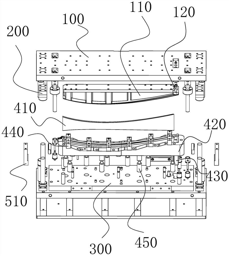
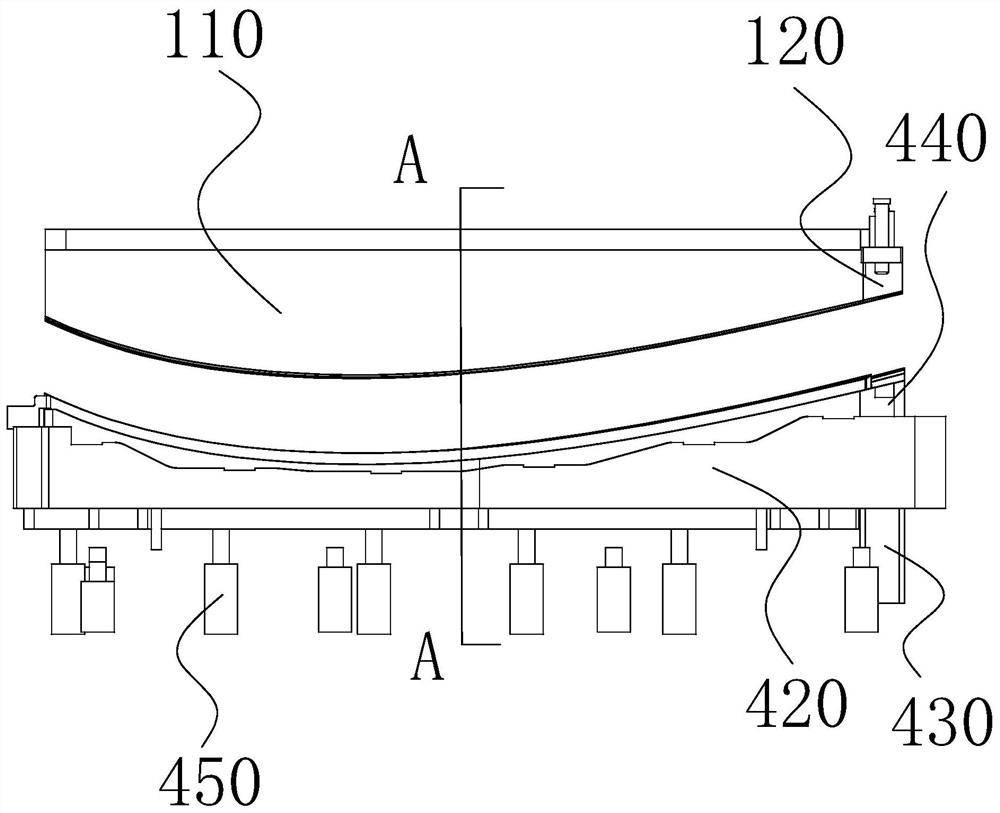
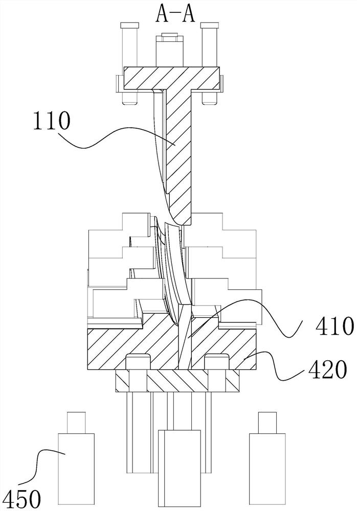
[0023] Such as Figure 1 to Figure 5 As shown, the double elastic binder end stretching equipment includes an upper fixed plate 100, a mold core 110, a lower elastic top block structure, and a mold base 300 arranged in sequence, and a guide rail is connected between the upper fixed plate 100 and the mold base 300. Column 200, the mold core 110 is installed on the end surface of the upper fixing plate facing the mold base, the lower ejection block structure is installed on the end surface of the mold base facing the upper fixing plate, and the lower ejection block structure includes at least T...


PUM

PropertyMeasurementUnit
lengthaaaaaaaaaa

Abstract

The invention provides double-spring material pressing end stretching equipment and belongs to the technical field of automobile part machining equipment. The double-spring material pressing end stretching equipment comprises an upper fixing plate, a mold core, a lower spring jacking block structure and a mold base, wherein the upper fixing plate, the mold core, the lower spring jacking block structure and the mold base are sequentially arranged. Guide pillars are connected between the upper fixing plate and the mold base. The mold core is mounted on the end face, facing the mold base, of theupper fixing plate. The lower spring jacking block structure is mounted on the end face, facing the upper fixing plate, of the mold base and comprises two or more lower spring jacking blocks. The moldcore and the lower spring jacking block structure form a cavity used for containing a product. The lower surface of the mold core is matched with the upper surface of the lower spring jacking block structure. A stretching block is movably arranged at the position, corresponding to a product stretching position, of the lower spring jacking block structure. An elastic material pressing structure ismounted at the position, corresponding to the stretching block, of the upper fixing plate. The elastic material pressing structure is arranged at the side of the mold core. The mold base is providedwith springs which provide jacking power for the lower spring jacking block structure. The double-spring material pressing end stretching equipment has the advantages that the product surface qualitycan be guaranteed, and the production efficiency is improved.

Description

technical field [0001] The invention belongs to the technical field of auto parts processing equipment, and relates to a double-elastic binder end stretching device, in particular to a double-elastic binder end stretcher suitable for processing automobile decorative strips. Background technique [0002] With the rapid development of the automobile industry, people have higher and higher requirements for the appearance of automobiles. For any automobile functional parts, it not only requires its own basic functions, but also requires it to improve the fashion and aesthetic characteristics of the automobile. Adding decorative strips to the automobile body It can play a decorative effect on the appearance of the whole car. [0003] There are two kinds of materials for car decoration strips: stainless steel and plastic. In order to improve the appearance of the car, stainless steel is generally selected. Currently on the market, the production process of stainless steel automot...

Claims


Application Information

Patent Timeline
Patent Type & Authority Patents(China)
IPC IPC(8): B21D37/10B21D25/00B21D53/88
Inventor 吕忠义
Owner NINGBO HONGXIECHENG AUTO PARTS CO LTD
Learn More