
A pixel matrix circuit applied to image sensor

An image sensor and pixel matrix technology, applied in the field of image sensors, can solve problems such as fixed pattern noise, inconsistency of voltage signals, affecting the quality of HDR composite images, etc., to achieve the effect of eliminating fixed pattern noise and facilitating deployment

Active Publication Date: 2021-08-10
THE 44TH INST OF CHINA ELECTRONICS TECH GROUP CORP
View PDF0 Cites 0 Cited by
  • Summary
  • Abstract
  • Description
  • Claims
  • Application Information

AI Technical Summary

Problems solved by technology

The above method is widely used in image sensors with unilateral output of the pixel matrix, but since there is still an IR-drop effect on the connecting wire between the pixel current bias and the output of the pixel unit, if the readout circuit is arranged at the end of the pixel current bias ( That is to say, the arrangement of the upper and lower readout circuits described above), the voltage signal at the output terminal of the pixel unit, the voltage signal at the upper and lower output terminals of the matrix column will still be inconsistent, thereby introducing fixed pattern noise, and finally affecting the HDR composite image the quality of
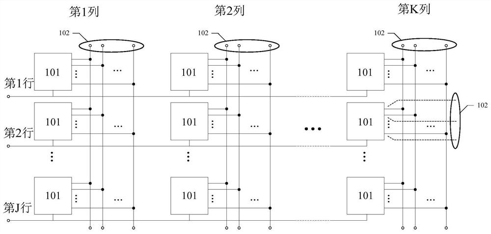
[0006] The present invention proposes a pixel matrix circuit applied to an image sensor, which can solve the inconsistency between the voltage signal at the output end of the pixel unit in the pixel matrix and the voltage signal at the upper and lower output ends of the column to which the pixel unit belongs

Method used


Image

  • A pixel matrix circuit applied to image sensor
  • A pixel matrix circuit applied to image sensor
  • A pixel matrix circuit applied to image sensor

Examples


Embodiment 1

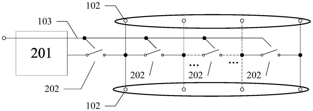
[0030] The example is Figure 4 As shown, for the sake of illustration, there are only two rows of pixel units in any column of pixels in the pixel matrix in the figure, and the two pixel units may be adjacent or not adjacent in the row direction; the pixel unit includes a core pixel circuit and N A switching device, the output end of the core pixel circuit is connected to the input end of the first switching device, the output end of the nth switching device is connected to the input end of the n-1th switching device, and the output end of the nth switching device is connected to The input terminal of the n+1 switch device is connected; the connection point between the first switch device and the second switch device is the first external output terminal, and the connection point between the n switch device and the n+1 switch device is The nth external output terminal.

[0031] In this embodiment, for the convenience of description, each pixel unit is connected with two swit...

Embodiment 2

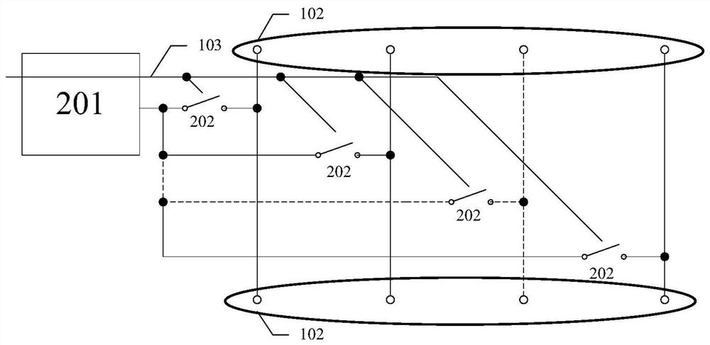
[0039] The example is Figure 5 shown. For ease of description, there are only two rows of pixel units in any column of pixels in the pixel matrix in the figure, and the two pixel units may be adjacent or non-adjacent in the row direction; the pixel unit includes a core pixel circuit and N switching devices, The output end of the core pixel circuit is connected to the input end of the first switch device, the input ends of the second to N switch devices are all connected to the input end of the first switch, and the output ends of the first to N switch devices are respectively 1 to N external output terminals; when the first switch device or any switch device in the nth switch device is closed, the external output terminal of the closed switch device outputs a signal, and the external output terminal of the disconnected switch device has no signal output.

[0040] In this embodiment, for the convenience of description, only as Figure 5 Show the connection between the jth r...


PUM


Abstract

The present invention relates to an image sensor, in particular to a pixel matrix circuit applied to an image sensor, including a pixel matrix circuit comprising a J×K pixel matrix M, a total of I pixel units, and the pixel unit M of the jth row and the kth column jk There are 1st to N external output terminals, and each external output terminal is connected to the pixel unit M of the j-1th row and the kth column (j‑1)k and the pixel unit M of the j+1th row and the kth column (j+1)k Connection; in the k-th column, the joint connection node of the nth external output terminal of the 1st to J rows is the nth external output terminal of the k-th column of the pixel matrix; the present invention realizes the voltage signal of the output terminal of the pixel unit, the pixel unit The consistency of the voltage signals of the upper and lower output terminals of the column can eliminate the fixed pattern noise caused by the inconsistency; the multi-configuration design and / or redundant design of the readout circuit provides greater convenience; two kinds of applicable pixels are provided The unit circuit structure is convenient to choose and deploy according to the actual situation.

Description

technical field [0001] The invention relates to an image sensor, in particular to a pixel matrix circuit applied to the image sensor. Background technique [0002] In the field of image sensors, a high-dynamic range (High-Dynamic Range, HDR) technology can effectively improve the dynamic range of an output image signal, and has been widely used. One of the methods to achieve HDR is: for the same image acquisition object, the image sensor outputs two or more image signals with different gains, and then synthesizes the two images into a single new image through a certain method inside or outside the sensor. The resulting new image has a higher signal dynamic range. Generally, image signals with high and low gains can be output separately in different frames or in different lines of the same frame, or can generate the output of different gains of the frame while generating a frame signal; the first two output methods will lose output speed or image accuracy, However, if you n...

Claims


Application Information

Patent Timeline
Patent Type & Authority Patents(China)
IPC IPC(8): H04N5/357H04N5/369H04N5/378
CPCH04N25/60H04N25/70H04N25/75
Inventor 刘戈扬
Owner THE 44TH INST OF CHINA ELECTRONICS TECH GROUP CORP
Learn More